German
Engine Test setup base carrier
Since I have to
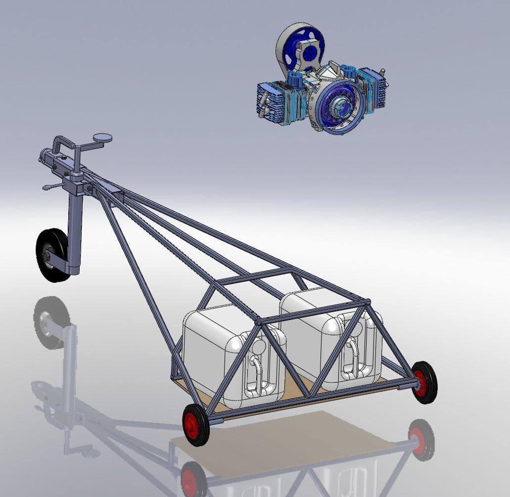
design the whole J5 Hirth F23 propulsion system from scratch, I need a
test setup where I can run and test the engine and its components.
First I need something where the test setup
can hold on. Ideal would be some concrete anchors with metal treats,
but our airport doesn't have this. Also running a 2 stroke engine for
hours in front of our house in the middle of the village might not
amuse the neighbours.A mobile solution is needed so that the whole thing can be transported to an industrial area or airport.
The idea is to have a test setup base, which can fit in into our VW Sharan family car. This base carrier has the trailer hitch as one fix point and stands on two wheels on the ground. Water canisters make the base heavy enough so that the propeller trust will not lift or move the test setup. Optional there can be a 16 mm steel rod be feed though the wheels 20 mm axles and affixed on the ground.
In order to start, welding equipment is needed. I did weld before when I modified my SF27M trailer,
but this was ages ago and a different welding method. I decided on WIG
welding equipment and thanks to Amazon was able to take of practice two
days later.
Somehow half of the welding equipment was protection gear (helmet, glows, arm protectors, protection skirt, ect. ...)
I'm lucky to have the groupMG in Wannweil as steel provider just around the corner! They are super friendly and ultra fast!
A friend who I used to know via the OUV showed me everything important about WIG welding. This enabled me a kick start into the WIG welding business.
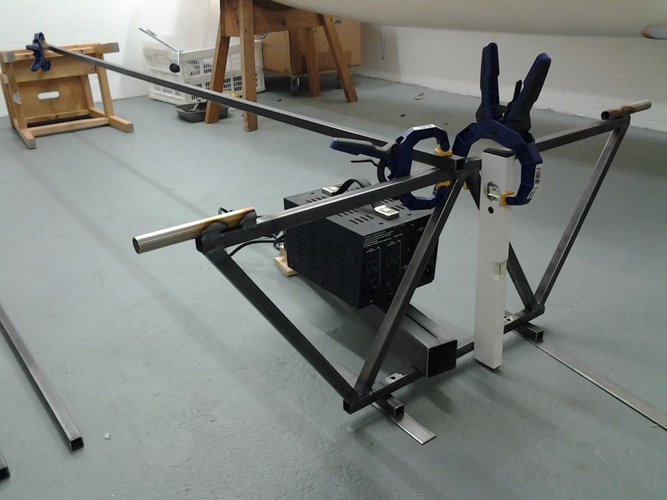
The engine test setup base provided the chance to practice the CAD and manufacturing of welding constructions.
For the precise alignment of the base I used an Bosch PLL 360 linie laser. This way you get a real strait reference line.
For the vertical alignment of the main bulkhead I simply use a water level.
Tim (2 weeks old) makes a nap. I wonder how old he will be at the time the J5 lifts of for the very first time.
I made a board for carrying the water
canisters. This board is attached to the frame by 7x M5 bolts. The
canisters are straped to the board and frame.
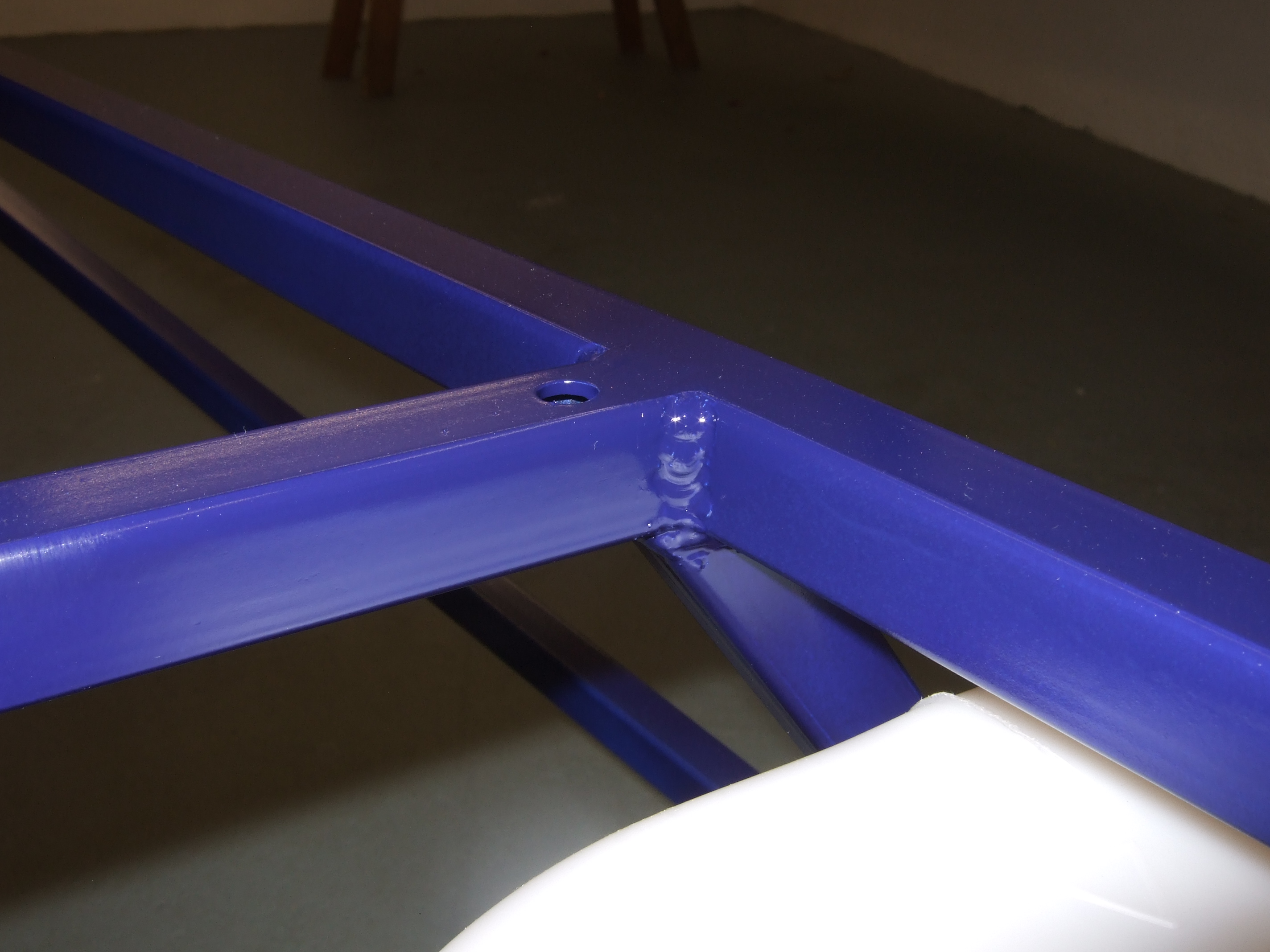
These are two welding closeups.
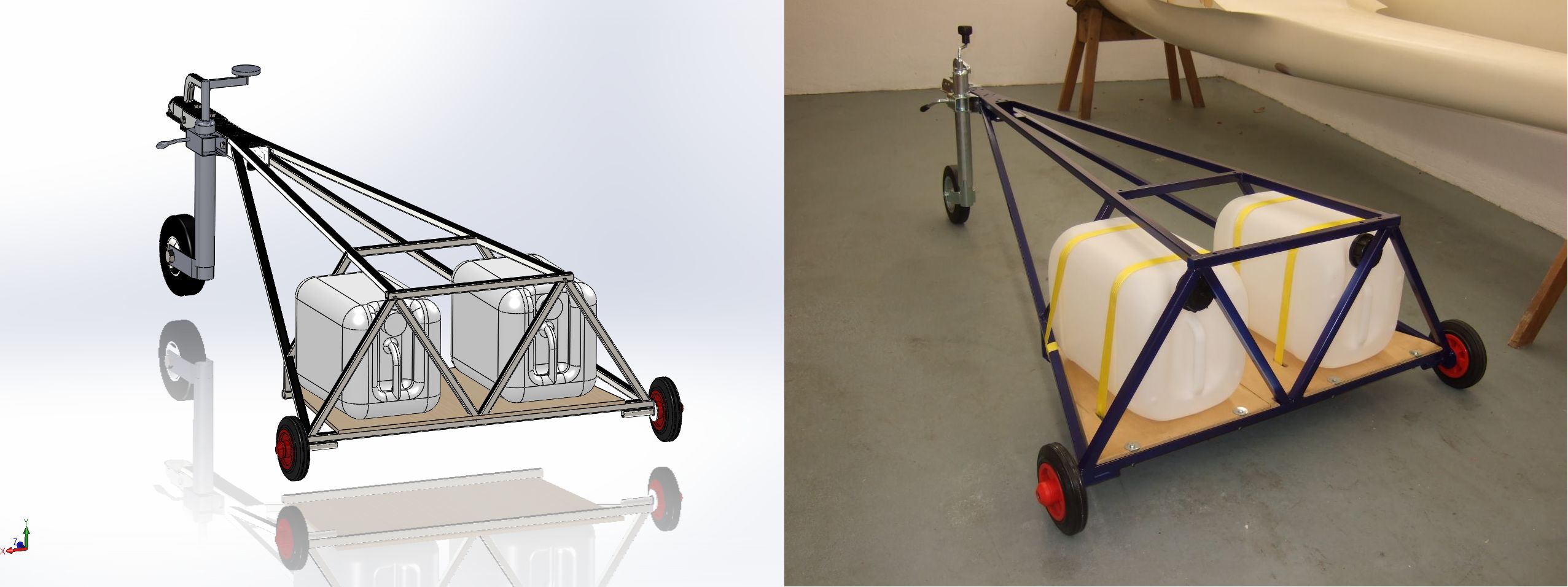
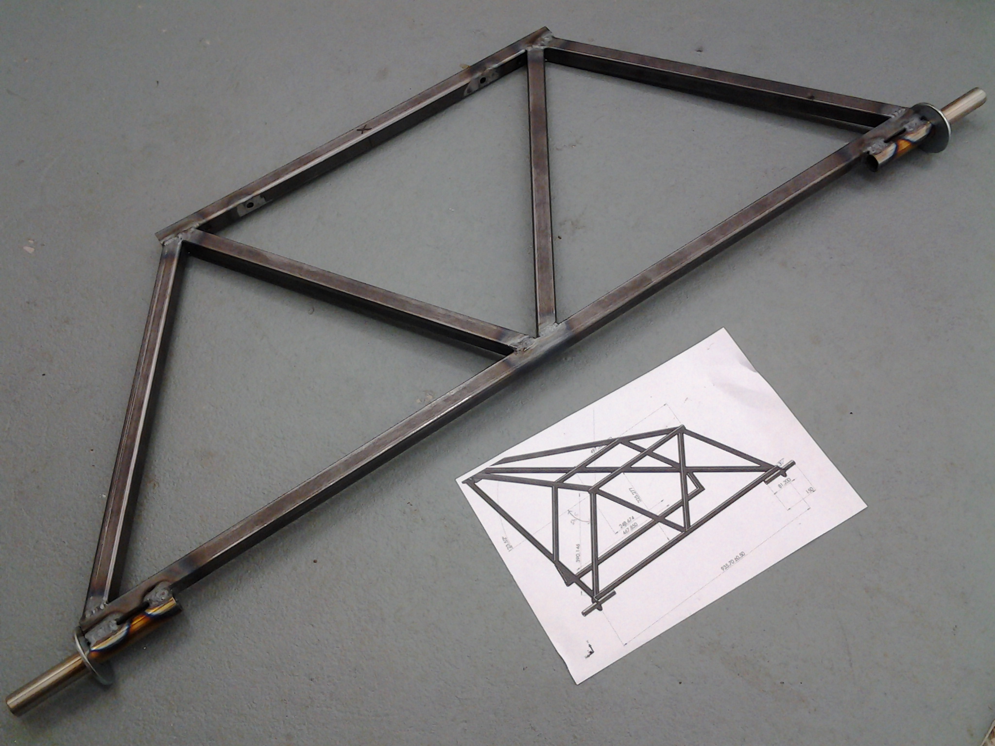
The last picture shows the CAD drawing and the final result.
Next I can design the principle propulsion design, which will be mounted onto this base carrier.
Impressum, Disclaimer & Datenschutz
 CAD drawing
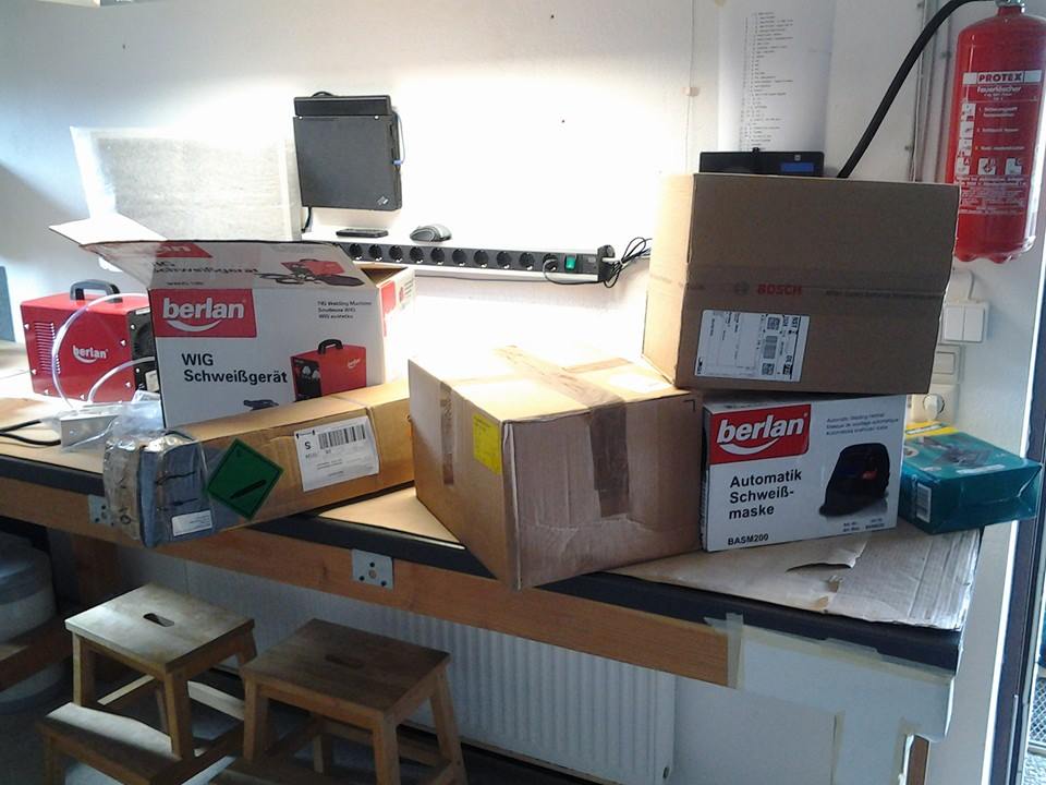
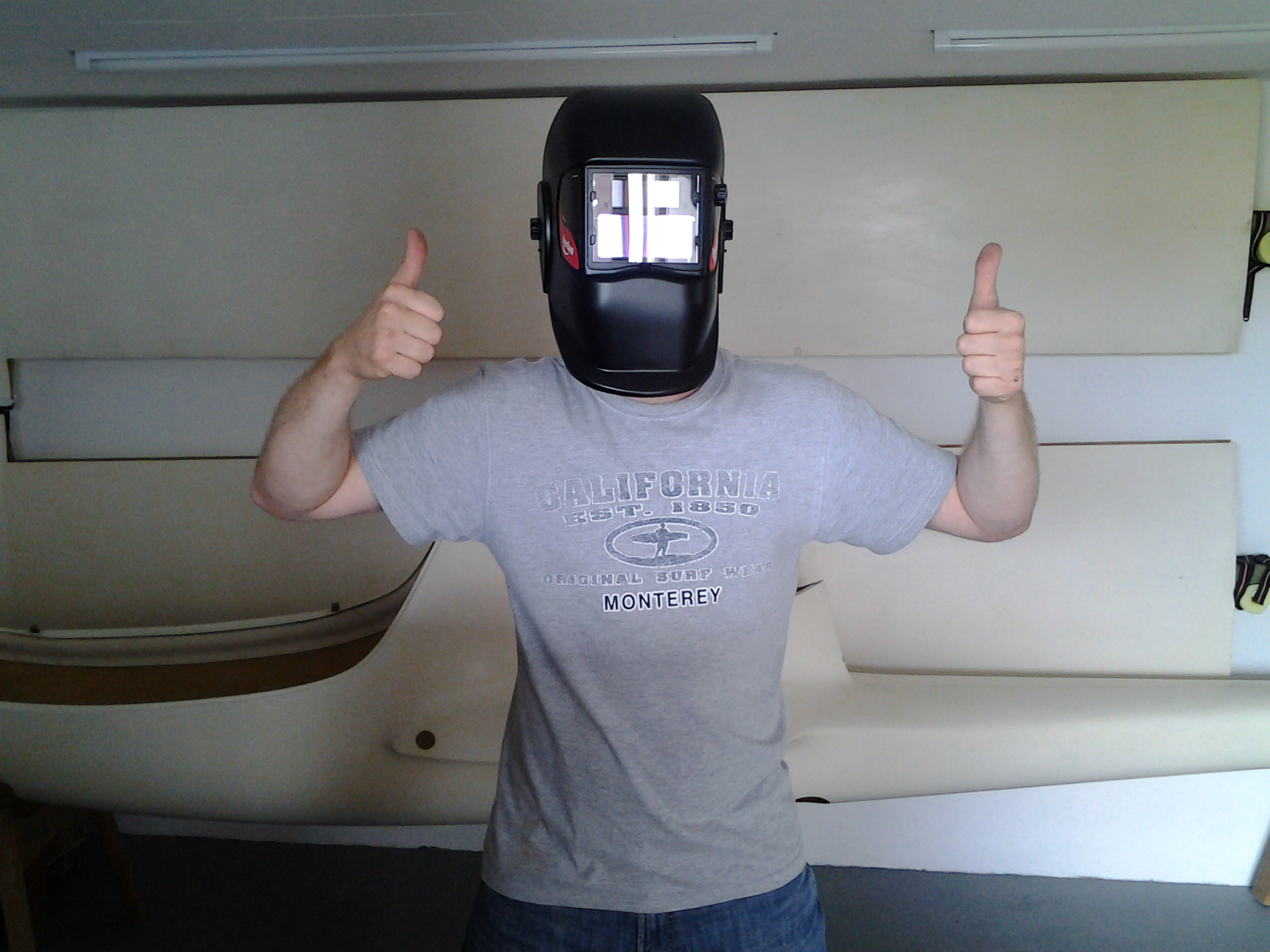 Welding Helmet
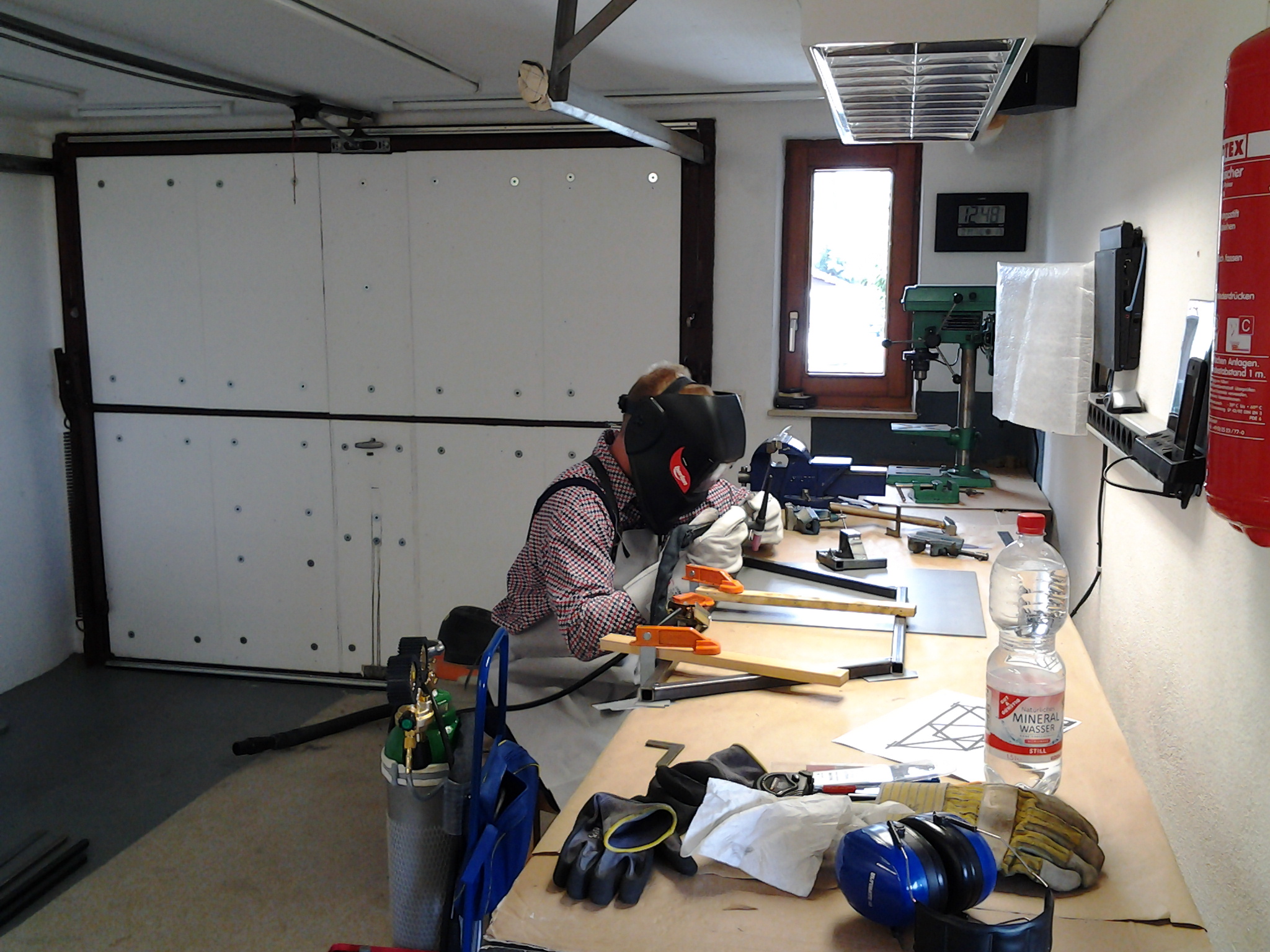
 main bulkhead
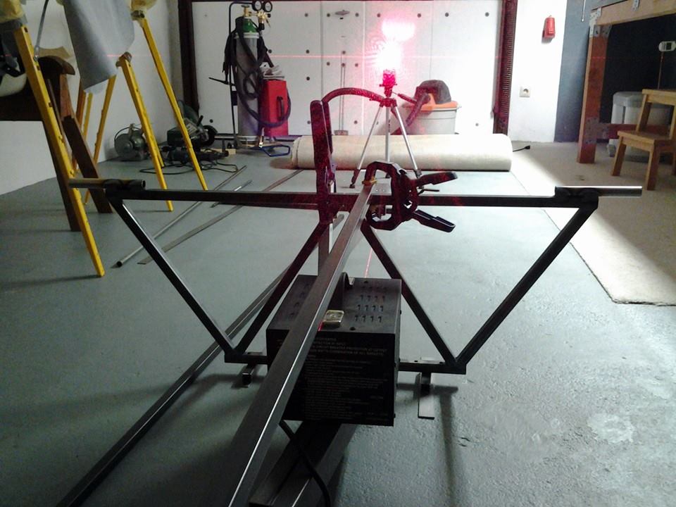
 don't shake!
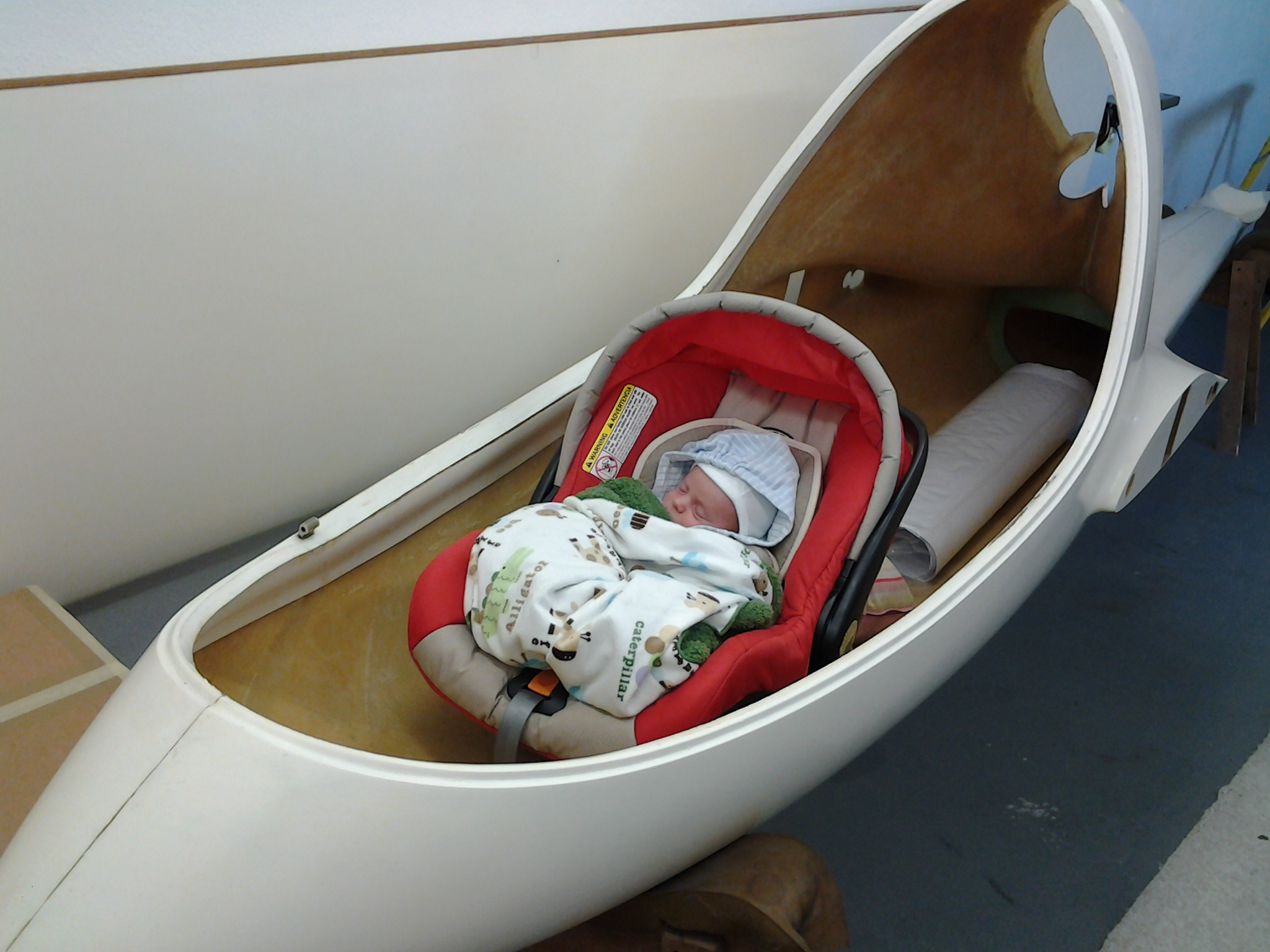
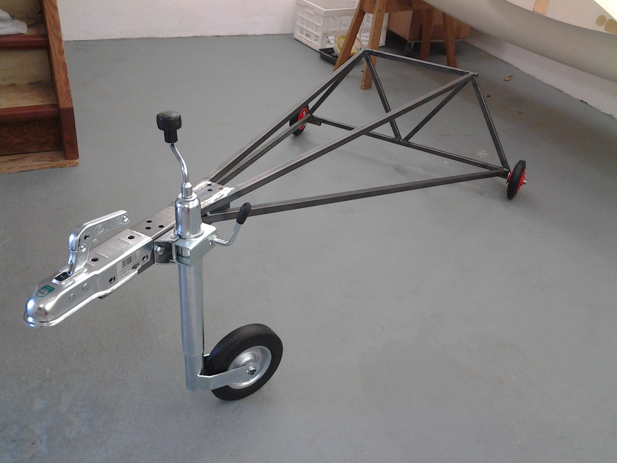 almost done
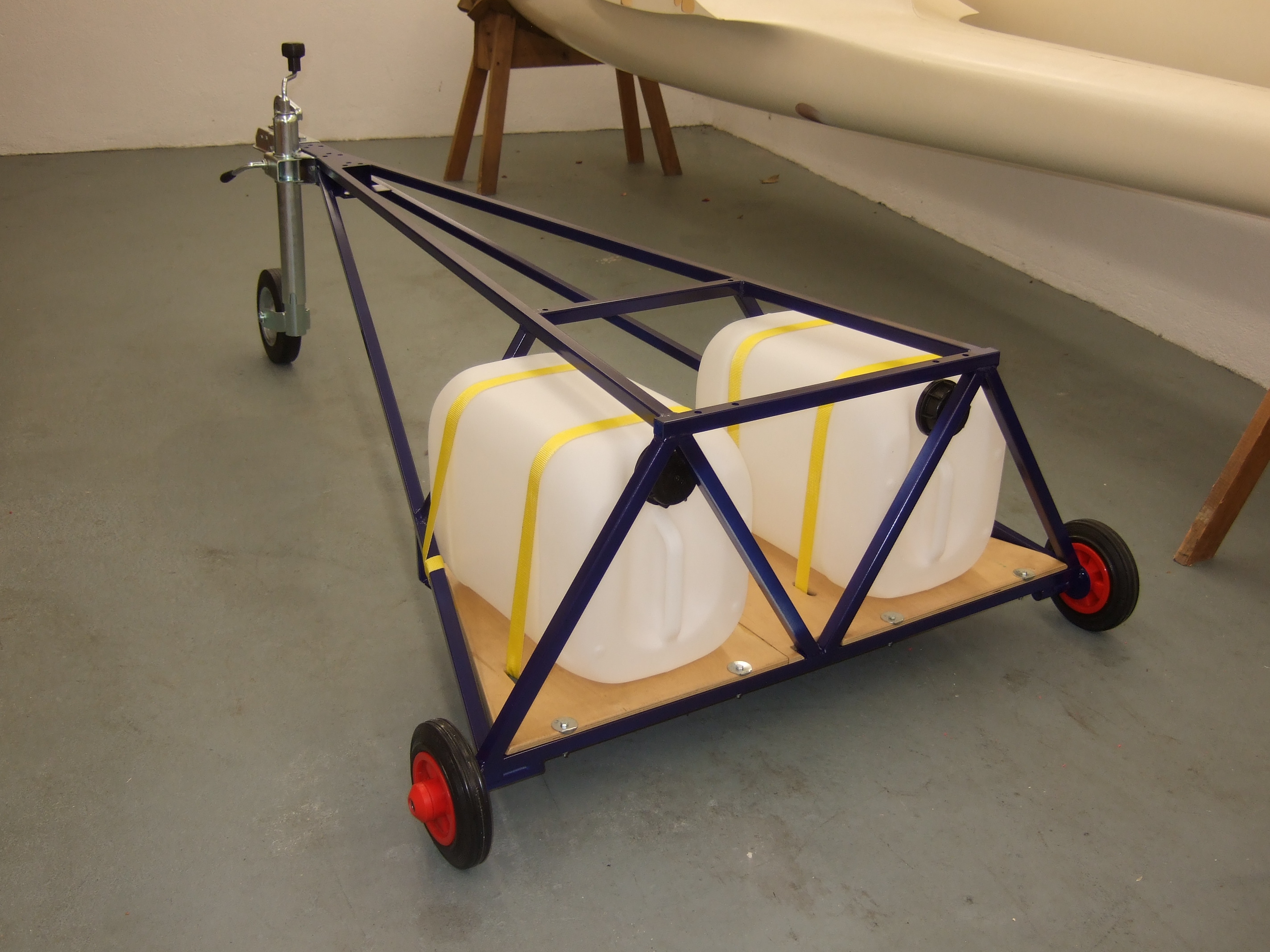
 welding example
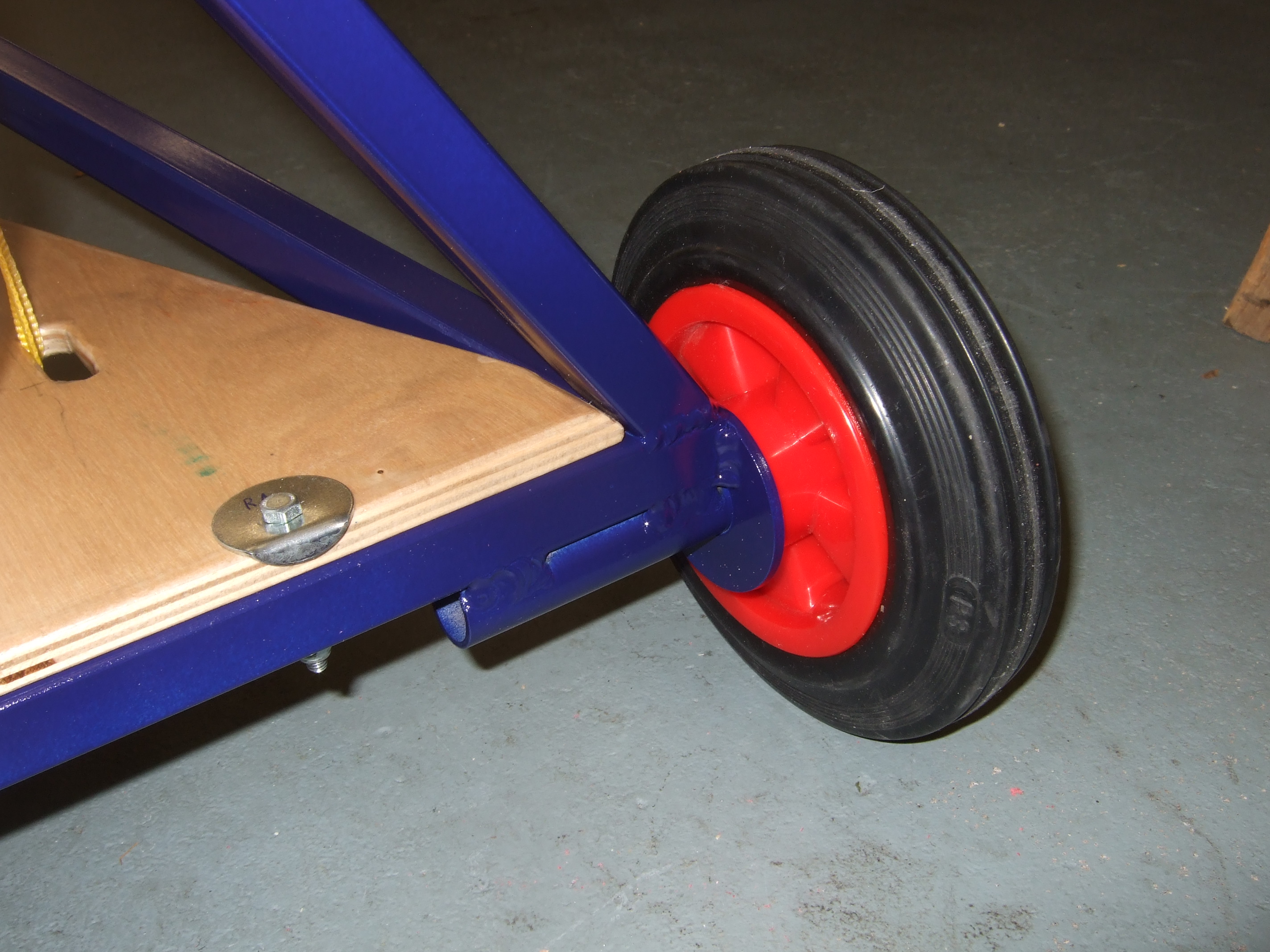
 J-5 Home