German
3D Modeling Details
Now I got a lot of modeling to do. This page will grow picture by picture, showing my progress.
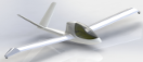
Now I have the task to design the engine installation. The wing penetrates the fuselage with its spar extensions. Modeling a dummy wing looked easy, but the wing tip and especially the wing tip wheel housing proofed challenging.
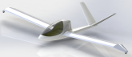
I outfitted the left wing with the spar extension, mirrored it, rotated the spar extension and wolla, I have a pair of wings. This make the whole thing start to look like an airplane.
One important thing for me is to track the accuracy between the model and the real thing. The ruler in the left picture shows 245 + 2 = 247 mm (the 2 mm because the ruler has the inner corner as reference). The CAD model show 252 mm at the same spot, which is 5 mm more. For a CAD manufacturing this would be unacceptable, but for planning the inner structure this is pretty good.
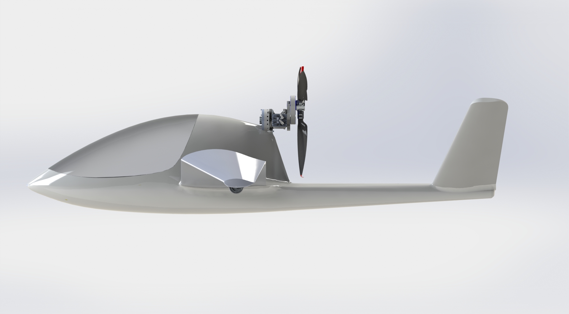
Now I got to decide a couple of important design parameter:
- propeller tip clearance behind the pot (cockpit)
- propeller tip clearance above the boom
- propeller inclination
- propeller deviation
These pictures shown a design where the propeller tip is 5 cm above and 10 cm behind the fuselage. The law required 26 mm radial and 13 mm longitudinal clearance. These values are easy to fulfill, but the question I'm asking is, whether noise can be significant reduced by increasing the distance behind the fuselage from let's say 10 cm to 20 cm?
Furthermore there is the question whether deviation is needed. The spiraling slipstream of a normal airplane hits the vertical stabilizer and generated a yaw moment which needs to be compensated by deviation. The J5 engine configuration doesn't know this problem. But still there is the torque generated by the propeller, which needs to be compensated by the ailerons. Ailerons always means adverse yaw, and here we get a yaw moment which needs to be compensated.
Compared to "normal" aircrafts the lever between the propeller and the center pressure is somewhat short for the J5 and so the deviation effect limited.
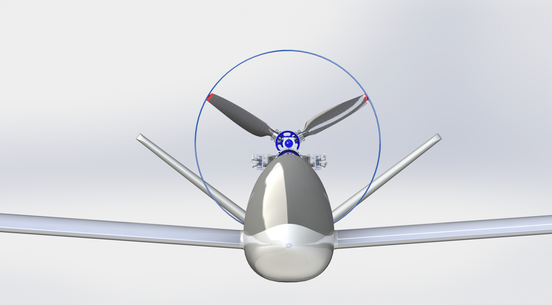
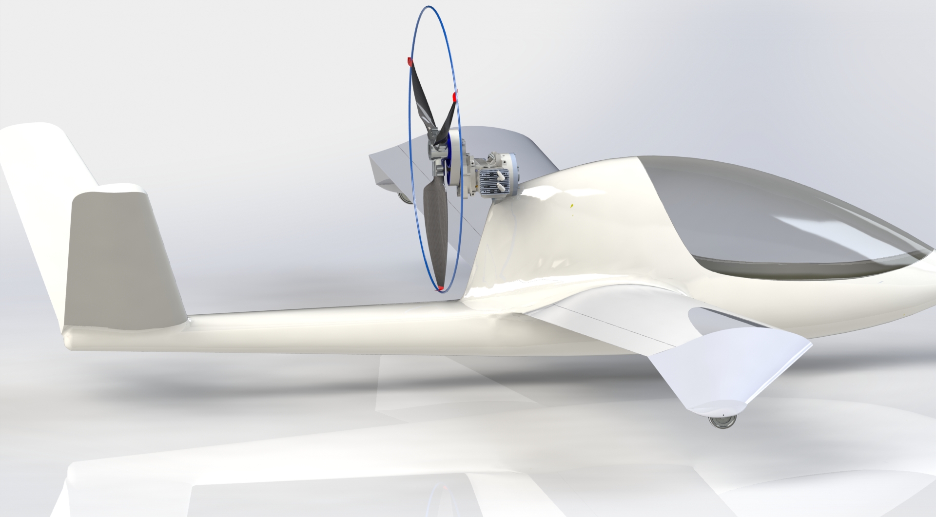
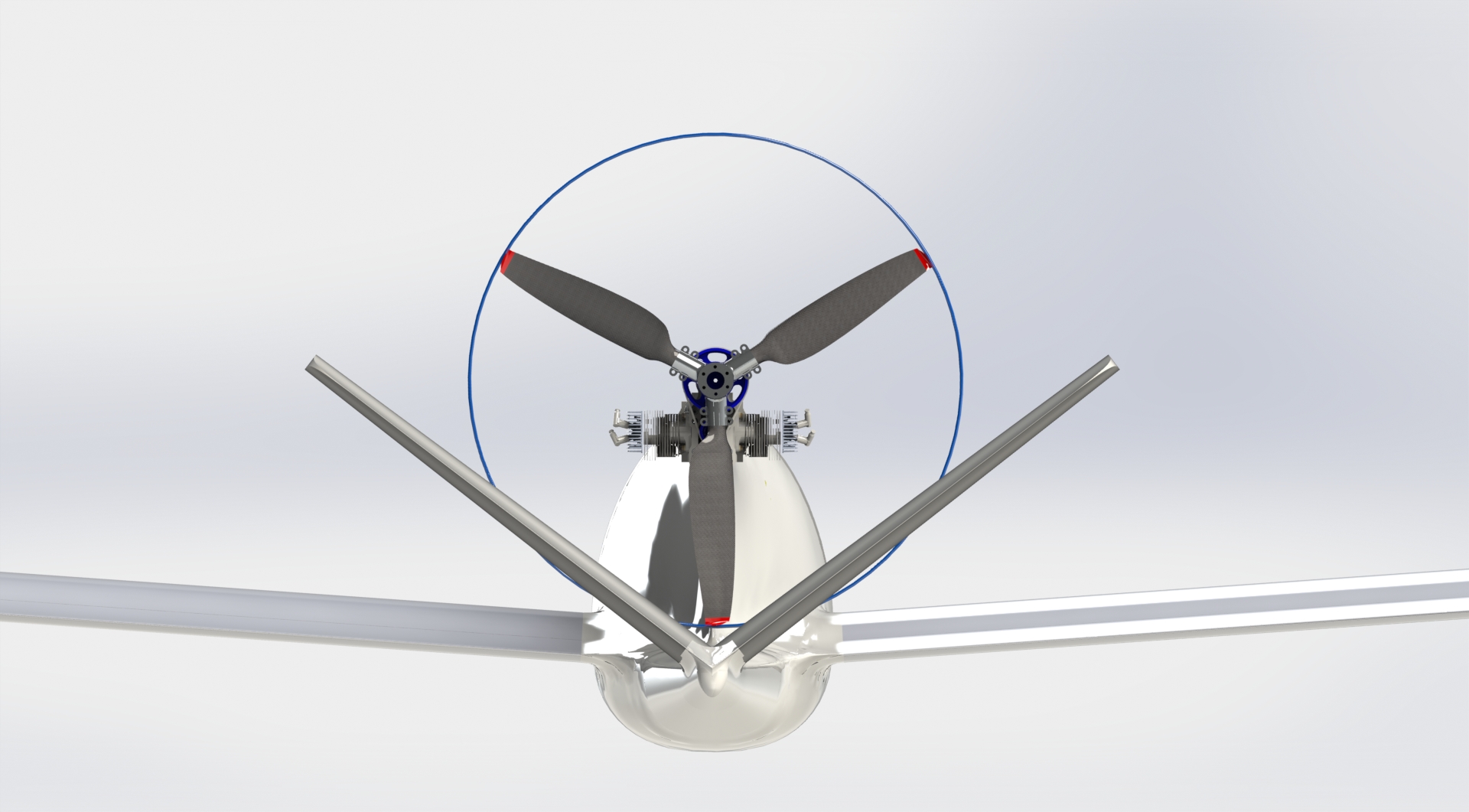
Another thing to consider for choosing the engine height is the intersection of the propeller circle and the V-tail. In my current design there is a slight intersection.
The task is to do the math for how much the slip stream will shrink on its way to the V-tail. Having Bernoulli in mind it is clear, that the static pressure in accelerated air is smaller and so the slip stream diameter has to shrink. Right now I'm looking for the equations to get a rough estimation. The parameters are:
- 1.36 m propeller diameter (WoodComp Winglet 136)
- 200 km/h air speed
- 30 kW engine power
- 2300 RPM propeller
- 1.5 m distance between propeller and V-tail
Should the math say that the slip stream shrink is more than 80%, then the V-tail would not be hit anymore.
There is still one more design parameter which can help to get clearance between the slipstream and the V-tail. Using some degrees of inclination will raise the slip stream above the V-tail. Regarding this I will have to read up a lot and also have to have discussions with experienced aircraft designers.
With all the things which can be calculated, only the flight test will reveal the truth. I will follow the advice of a aircraft building friend who told me to design in a way which enables me to chance the deviation and inclination with little effort. Well - it's still an experimental aircraft :-) .
To be continued...
Impressum, Disclaimer & Datenschutz
![]()