German
25% J5 RC Model
Designing the propulsion system, you have to decide the angles for the down thrust and side pull.
Talking to well known light sport aircraft designers I got answers ranking from "0° for both is good" to "..you need x° down thrust" to "... -x° down thrust" and "you HAVE to have x° side pull" to finally "..you have to try it..". Therefore I decided to go for a trial and to build a 25% RC model of the J5-Marko. This way I can figure out how important these two design parameters are.
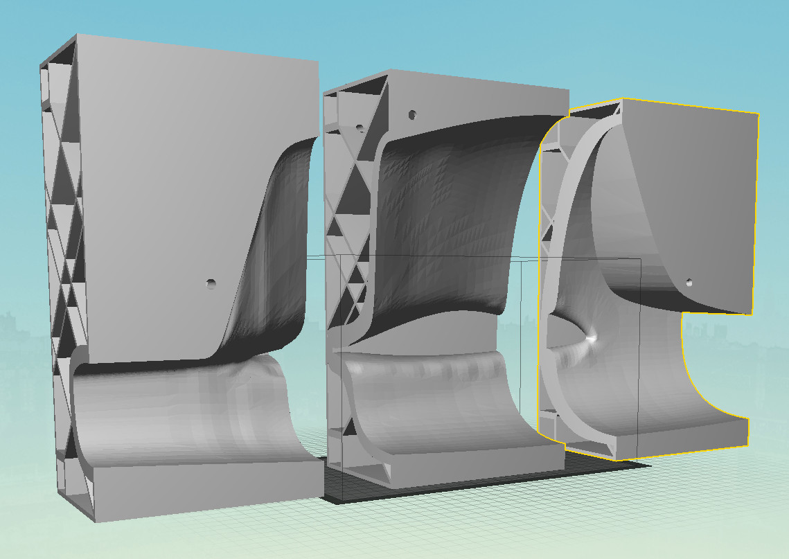
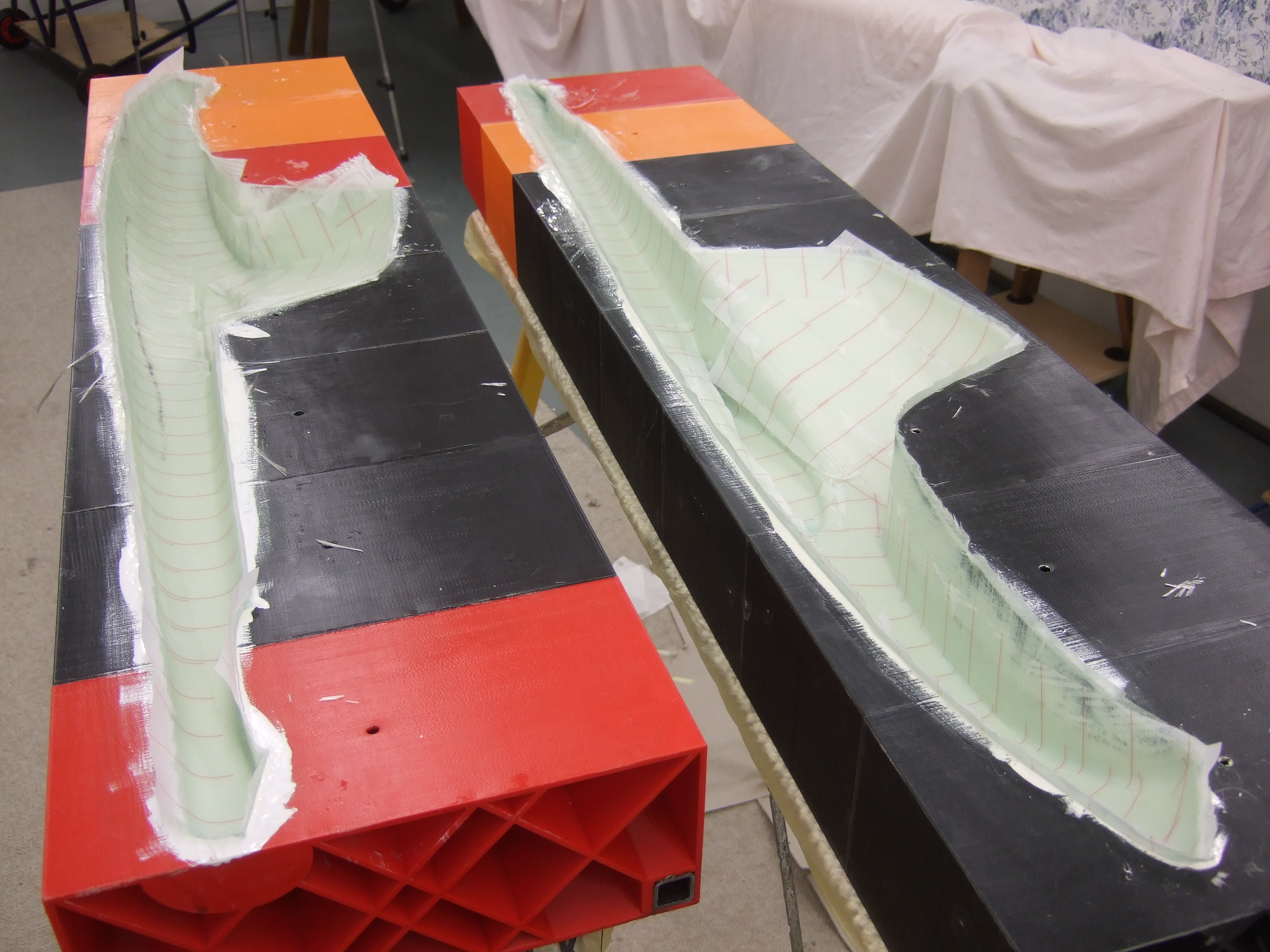
Since I have the 3D-Model of the fuselage, it was easy to generate the mold in 3D. All you have to do is to generate a second body with about 10mm offset and then subtract the fuselage from this body. This gives you the hollow mold body which you now have to cut in two half's. Since the mold would be too large for a normal 3D-printer, I split it up into 8 pieces. These 8 pieces are then then threaded onto two 20x20x2 mm steel profile rods. This way you get the resolution and accuracy of a 3D printer combined with the precision of a steel profile rod.
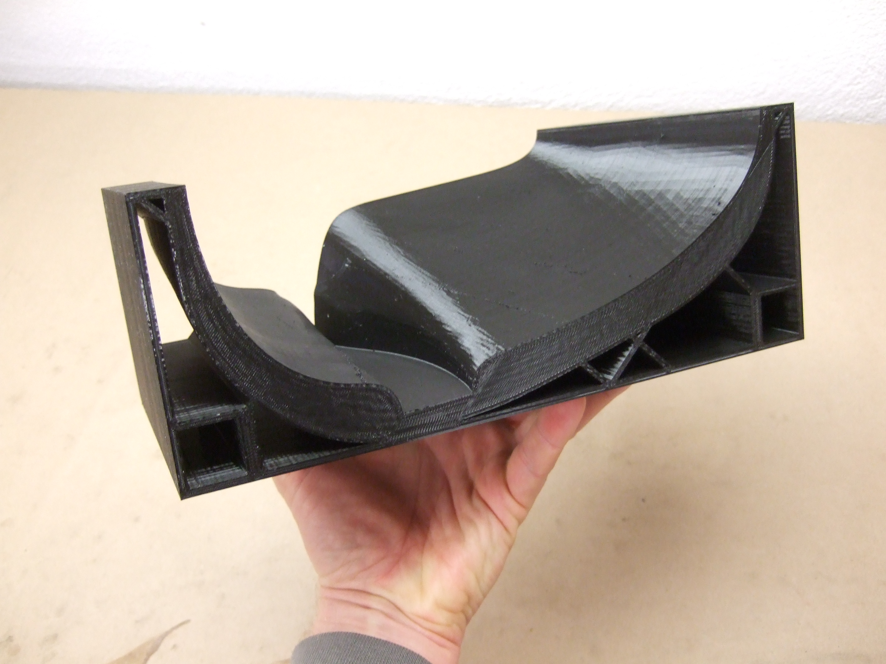
3D printed parts have typical print grooves. I oriented the part in a way so that these grooves are in the dismantle direction and not orthogonal to it, restraining the unmolding process. Imperfections can easily be removed with a draw blade.
All pieces are then threaded onto two 20x20x2 mm steel profile rods an glued together with instant adhesive.
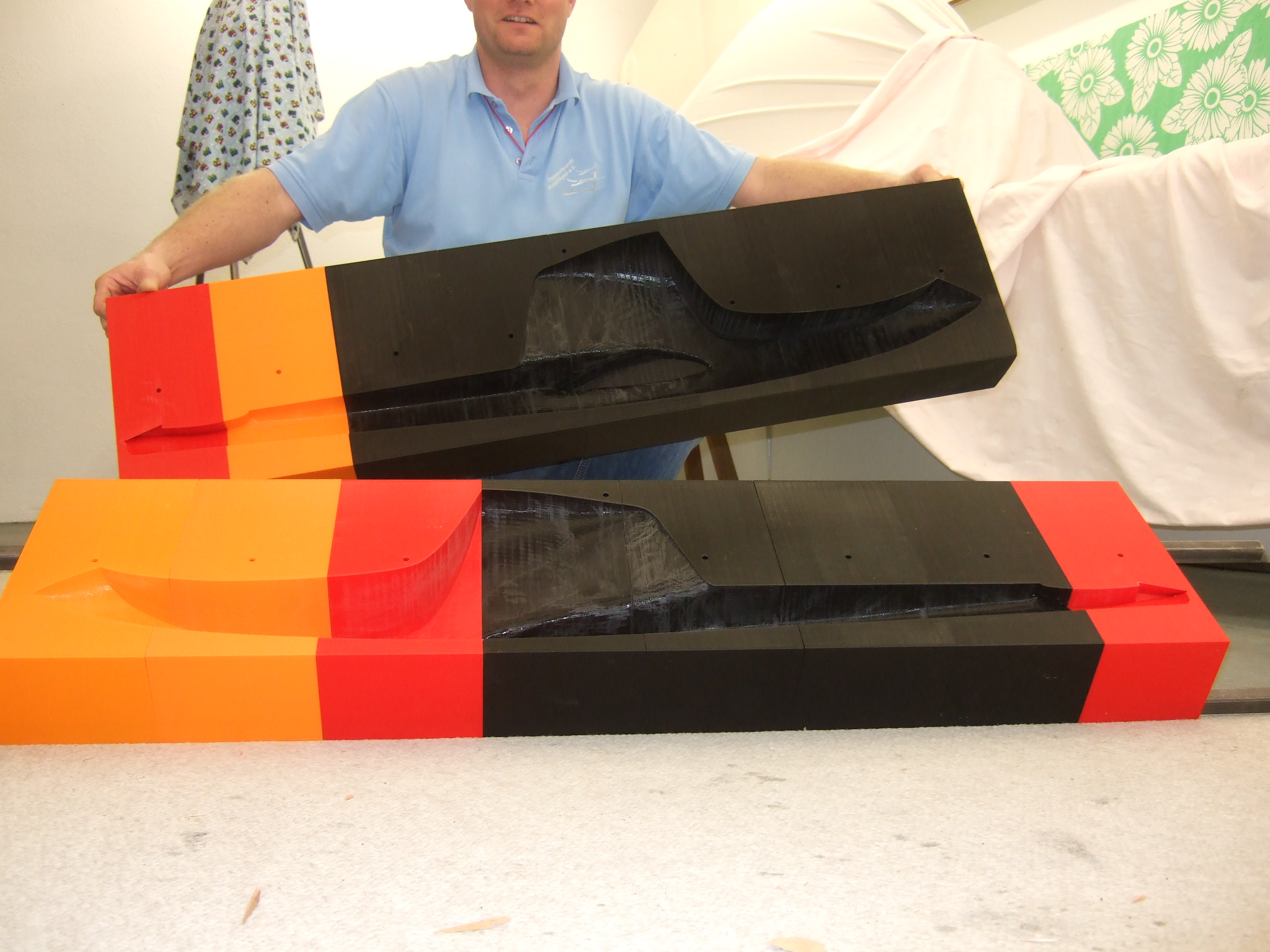
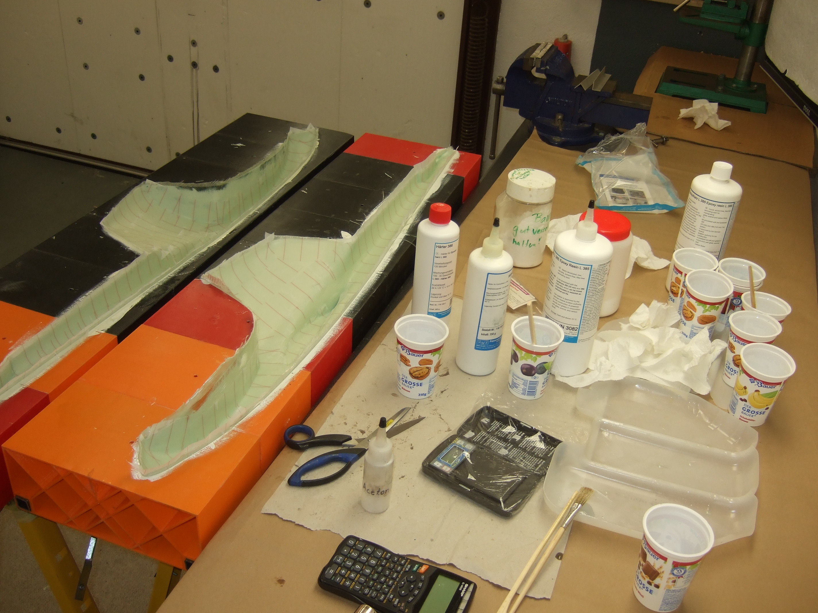
I waxed the mold several times and applied PVA film release agent. All material was supplied by R&G in Waldenbuch. I am so happy to have this supplier close by.
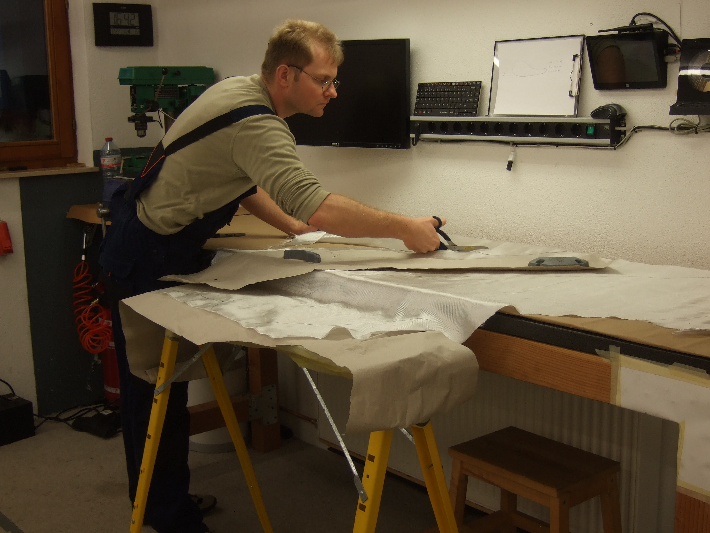
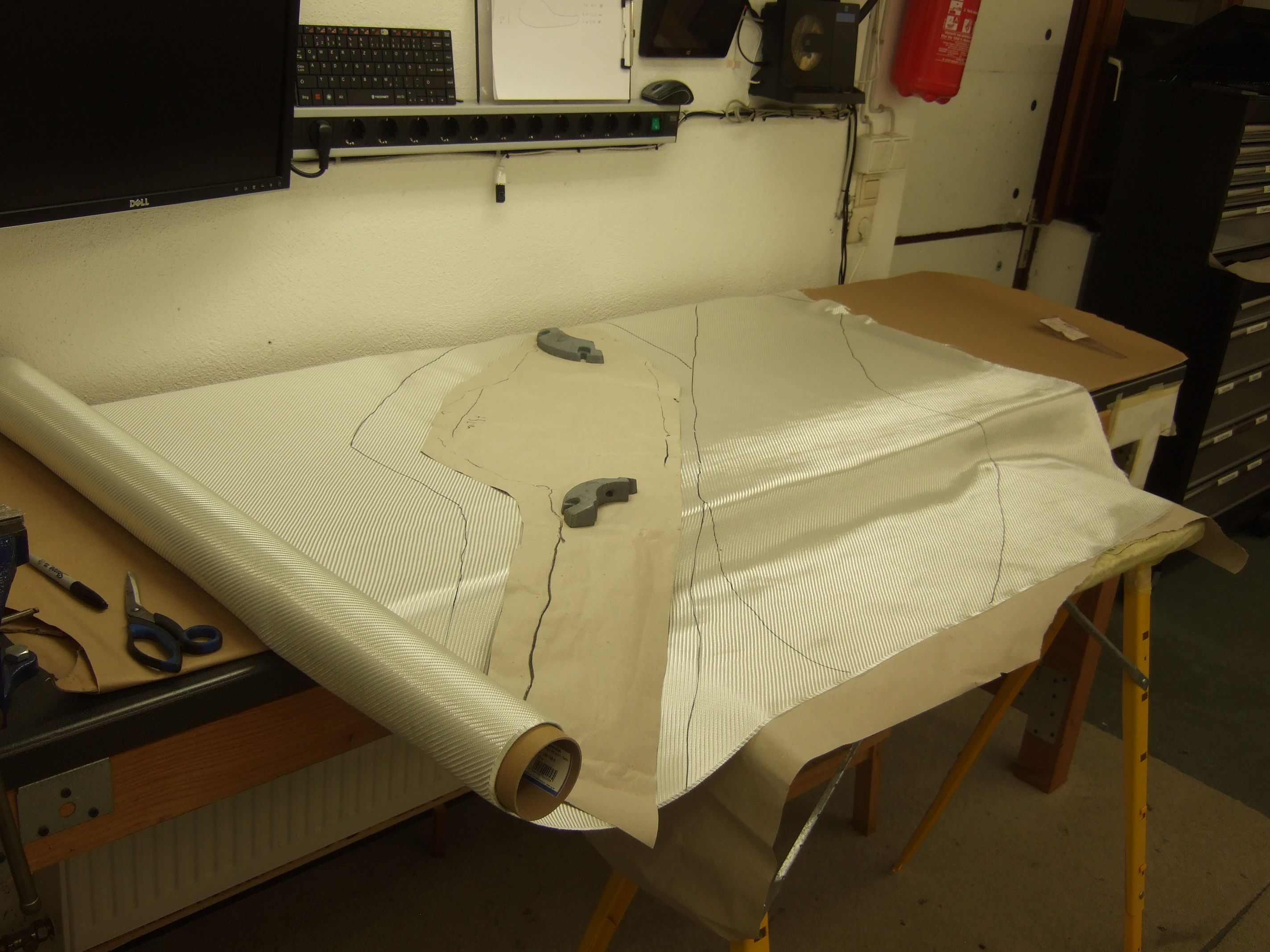
As for the ply configuration plan, I decided for the following:
1x X 160 g/m2
1x || 220 g/m2
1x X 280g/m2
I used this configuration for the entire fuselage. The weight of the glued fuselage halves summed up to 750 g.
If I build a second fuselage in the molds, I will decide to go more light weight, especially for the upper part of the pot:
1x X 160 g/m2
1x || 220 g/m2
1x X 160g/m2
I belief that this configuration would create a sufficiently strong fuselage below 500g weight.
The red striped cloth is peel ply. You rip it off after the resin cured and find a perfectly raff surface onto which you can glue immediately without sanding.
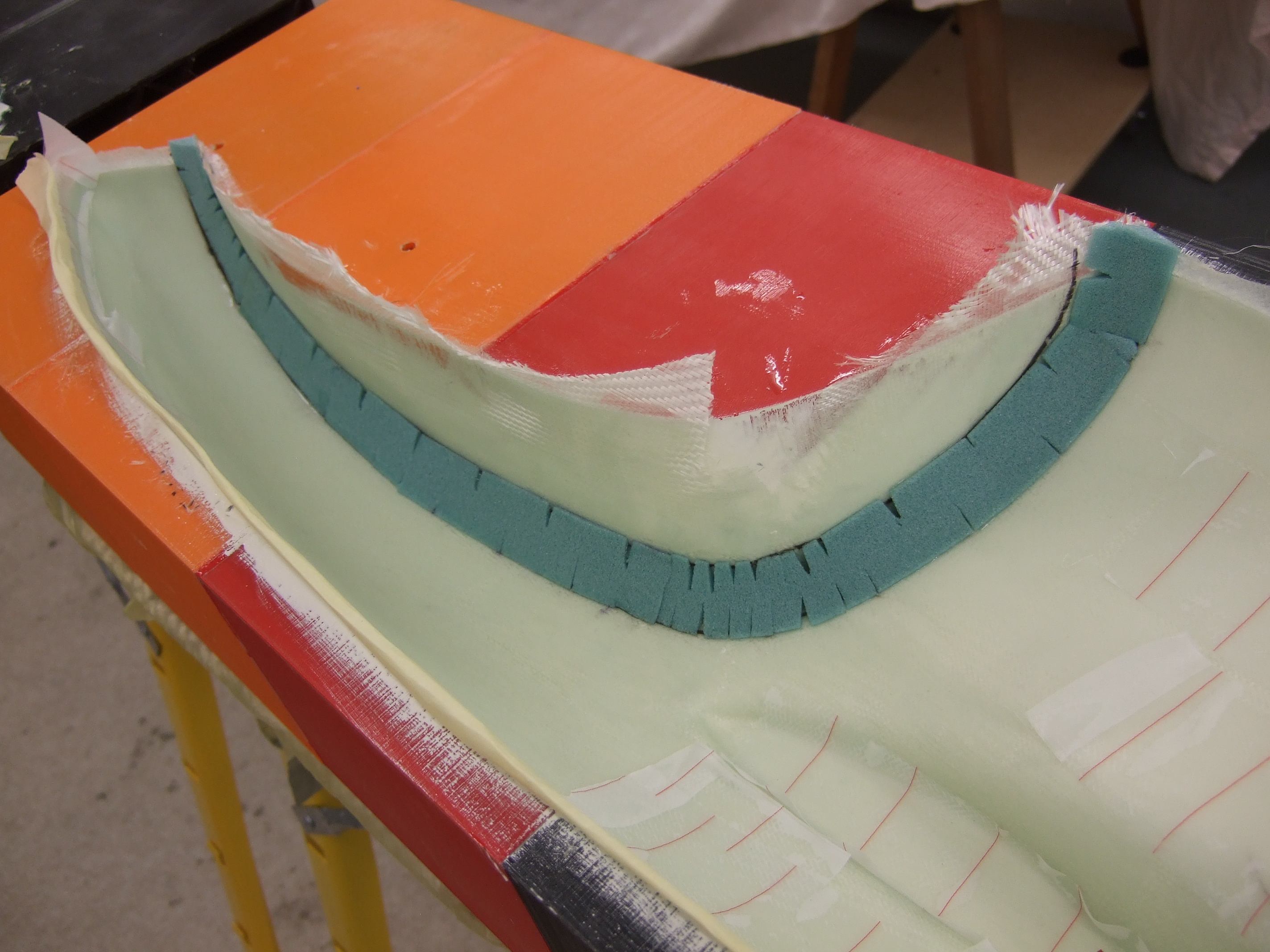
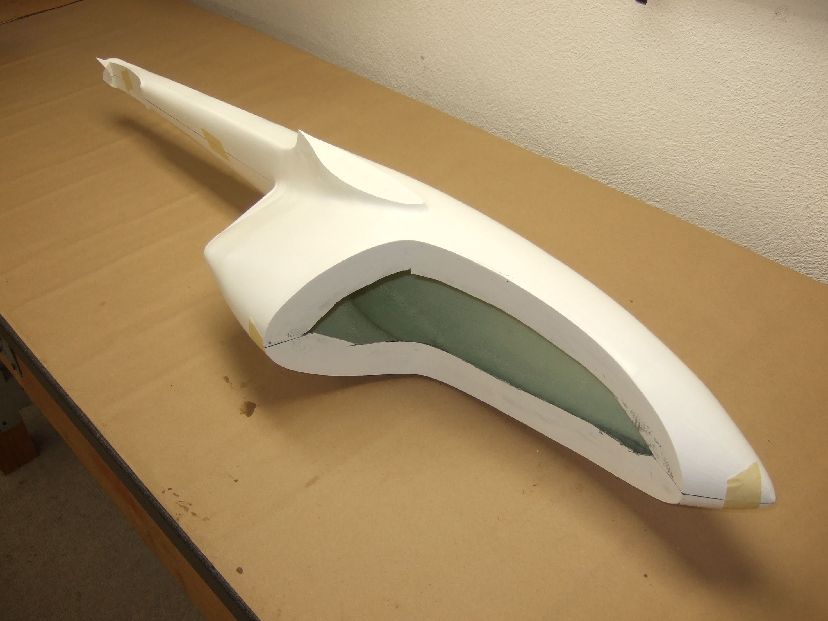
The J5-Marko has a very large canopy. Accordingly, there is a huge cutout for it in the fuselage. The cockpit would be very flabby without a stiff cockpit frame. In the case of a hard landing, the cockpit would buckle and break. This is also true when it comes to passive crash safety for the real J5. That is why I prepared two 15 mm wide, 6mm thick Conticell strips and created a trapeze shaped cross section canopy frame.
The cockpit frame has the following layer configuration:
1x X 280 g/m2
2x || 220 g/m2
1x X 280 g/m2
I used 10 mm overlap to the fuselage shell for the X oriented layers.
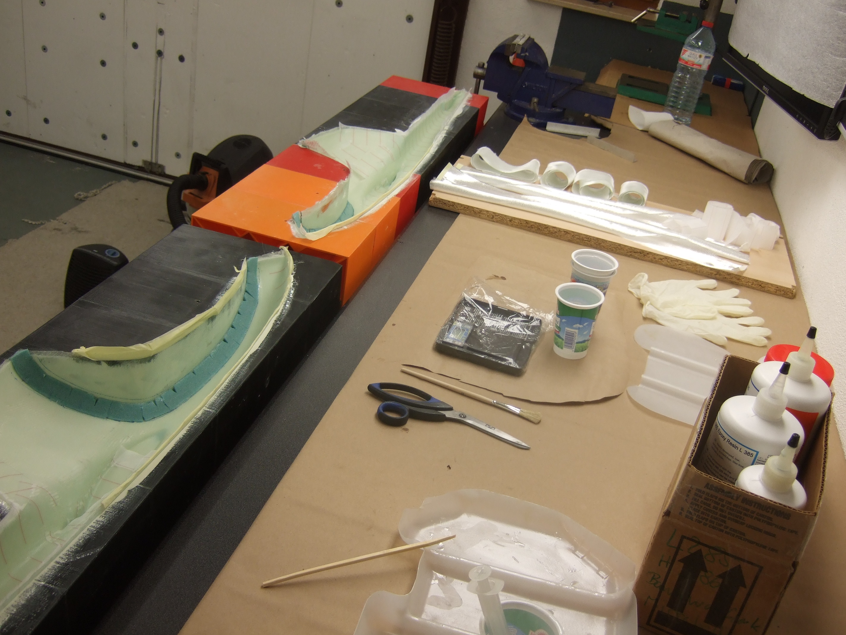
I glued the Conticell with hot glue in place. The Conticell provides only the shape. The hot glue cures so fast that you can hold the Conticell in place with your fingers and wait for it to cool. An important thing is, that you apply the hot glue only in the middle of the Conticell stripe and prevent it from dripping on any other areas, especially where you plan to epoxy something to.
Since PLA is not temperature stable, you can't post cure in the mold. Therefore it has to be post cured after completion. Since I used hardener H386, there is no way around it (H385 might have allowed not to post cure). However I decided for H386 since I hate to be in a rush while doing the layup (H386 has 2h pot life while it is only 30 min for H385).
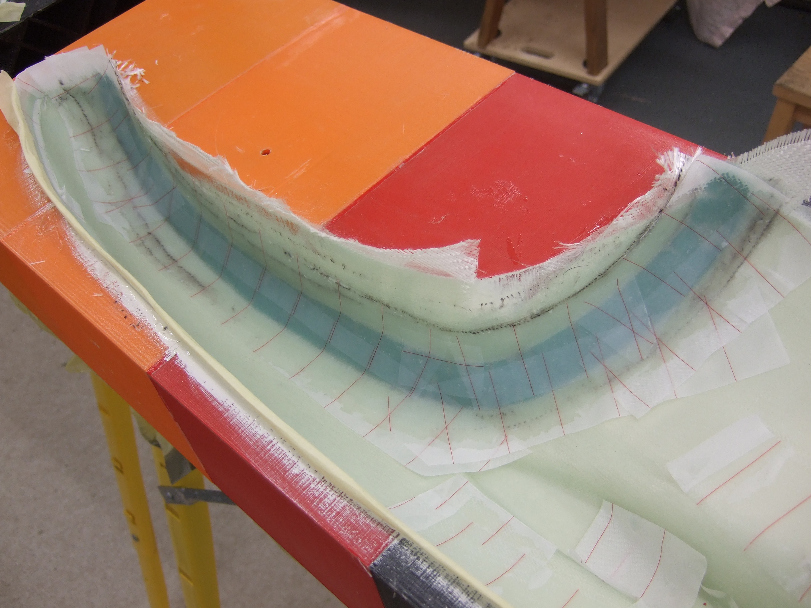
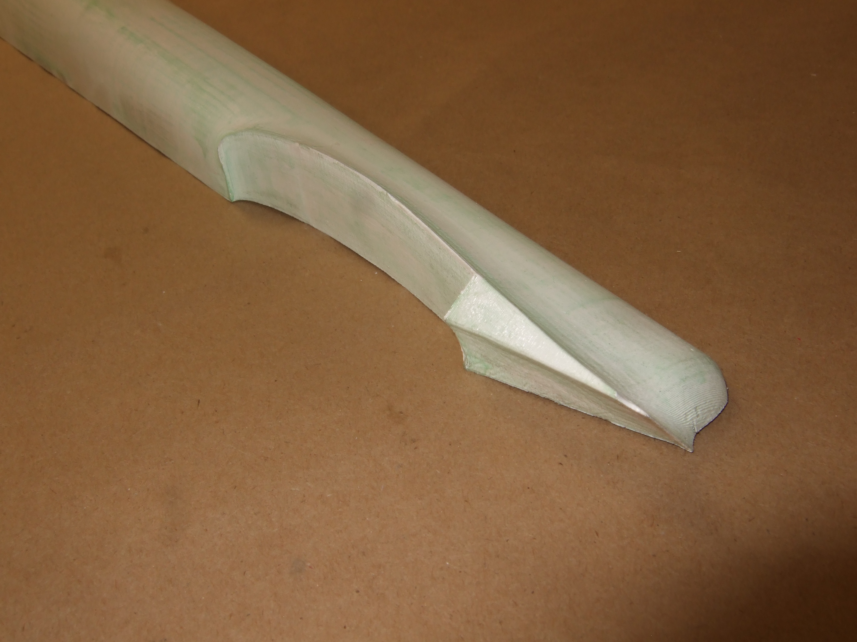
The stabilizer intersection has an undercut. I was worried that this would give me trouble while removing the part from the mold. Therefore I used only one layer 1x X 160g/m2 on this particular section. Luckily, this worked very well and removing the part from the mold was a piece of cake. Surprisingly the orthogonal cockpit frame proved to be a troublemaker. A draft has to be designed in for easy removal. At last, both pieces came out of the molds just fine.
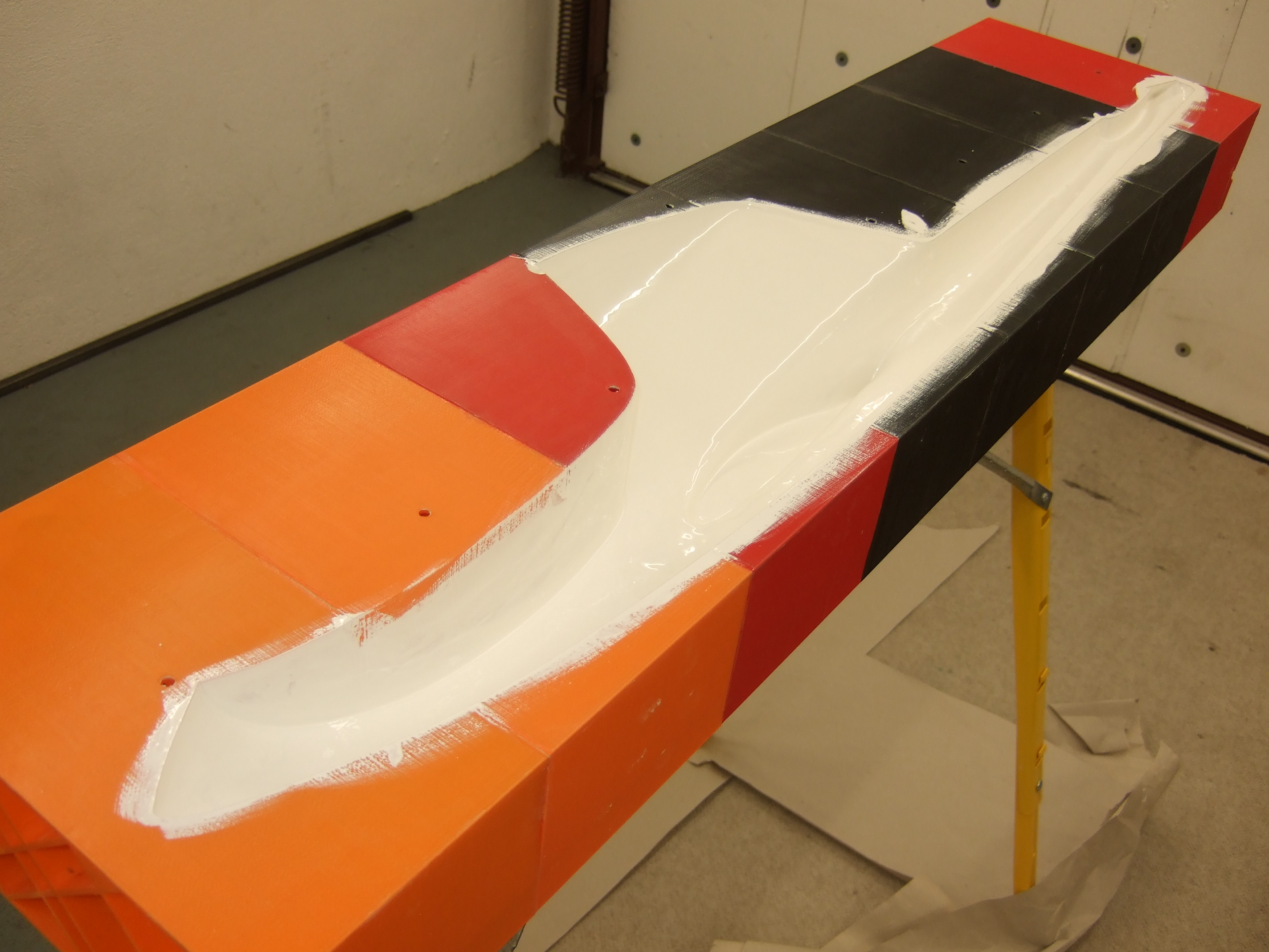
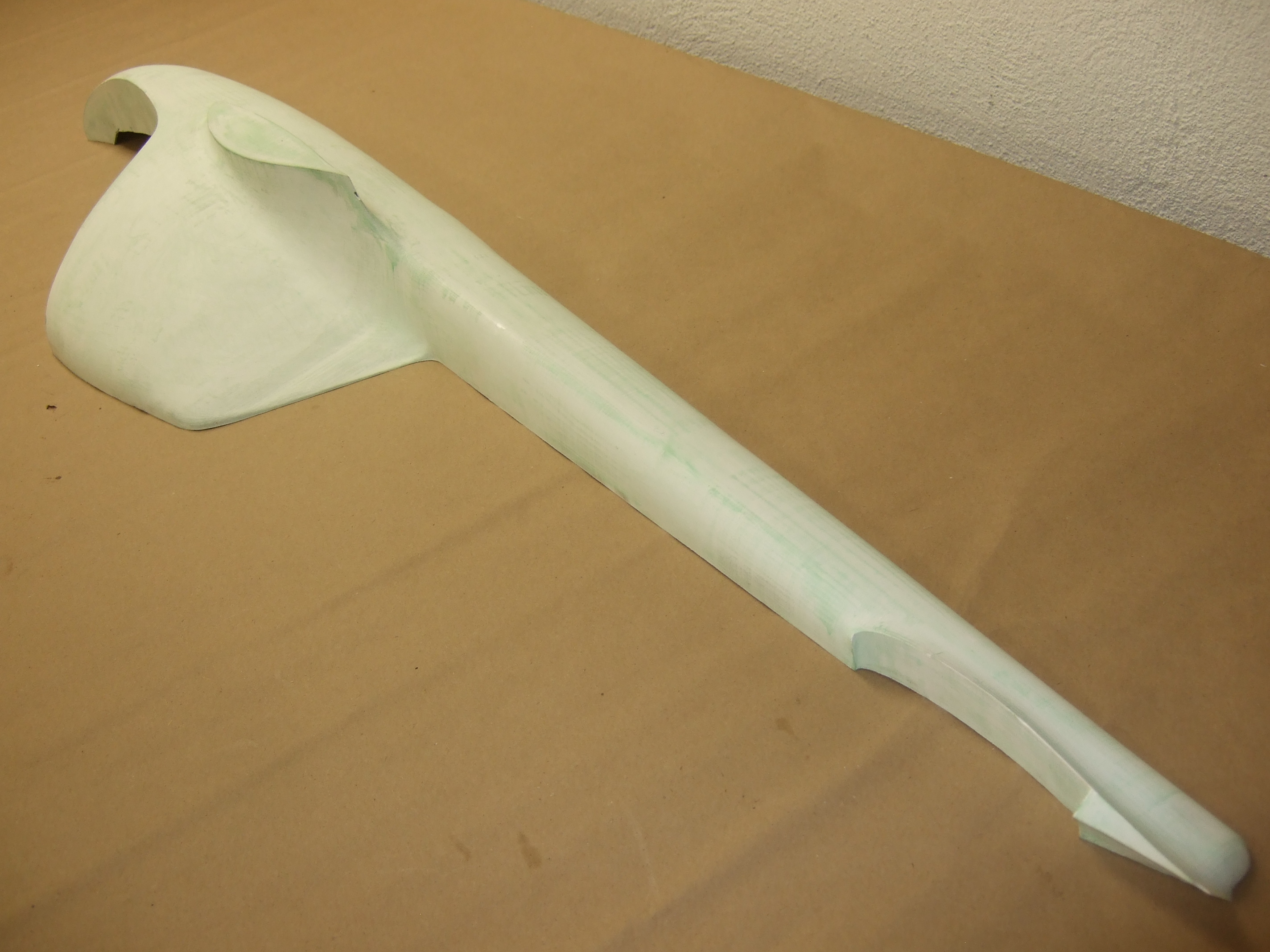
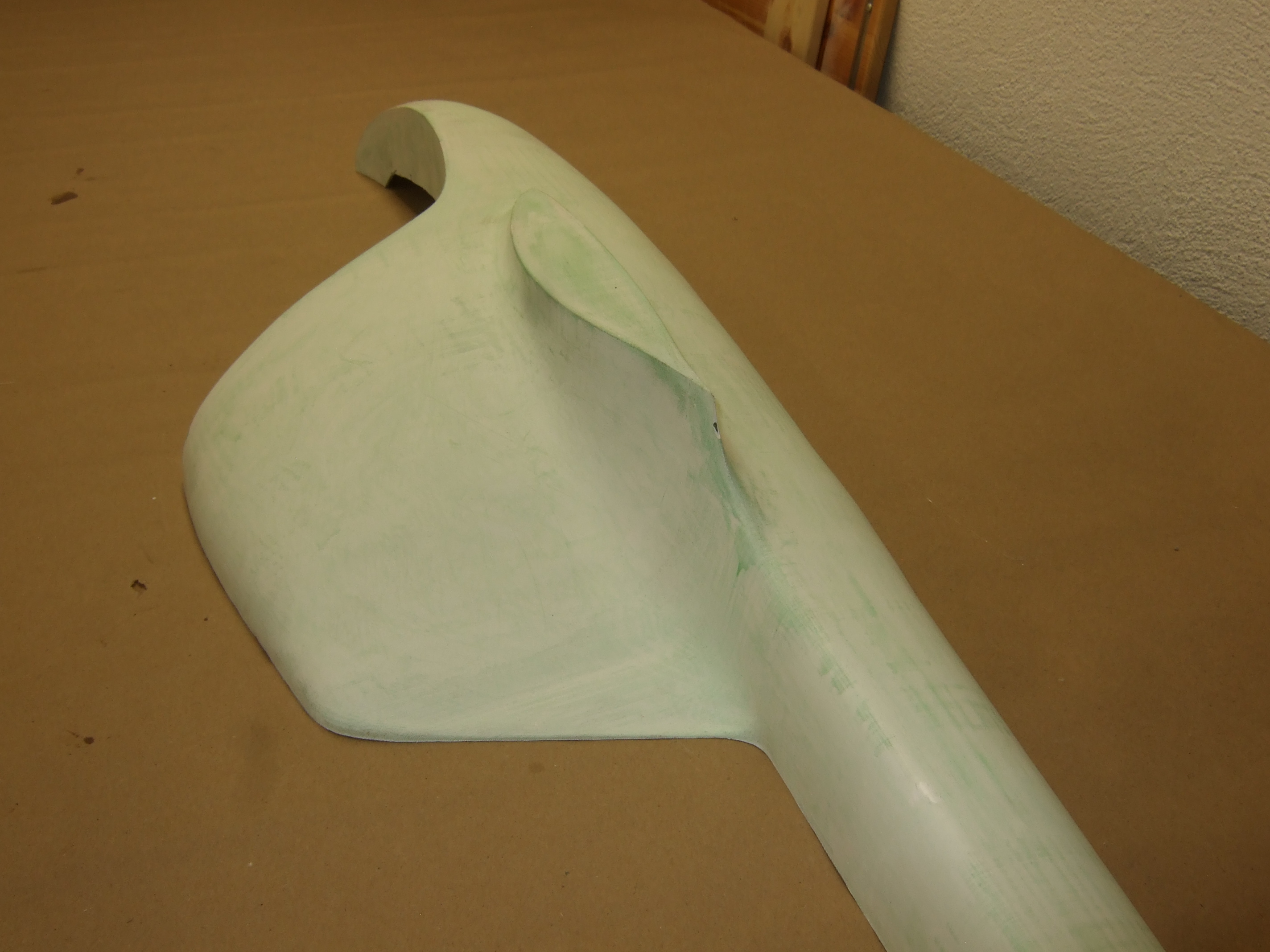
The picture above shows the wing fuselage intersection. This detail came out very nice. Despite my worries, only a small chip came of. The green stuff on the part is the PVA film release agent. This stuff can be washed away with water, which I did in our bathtub.
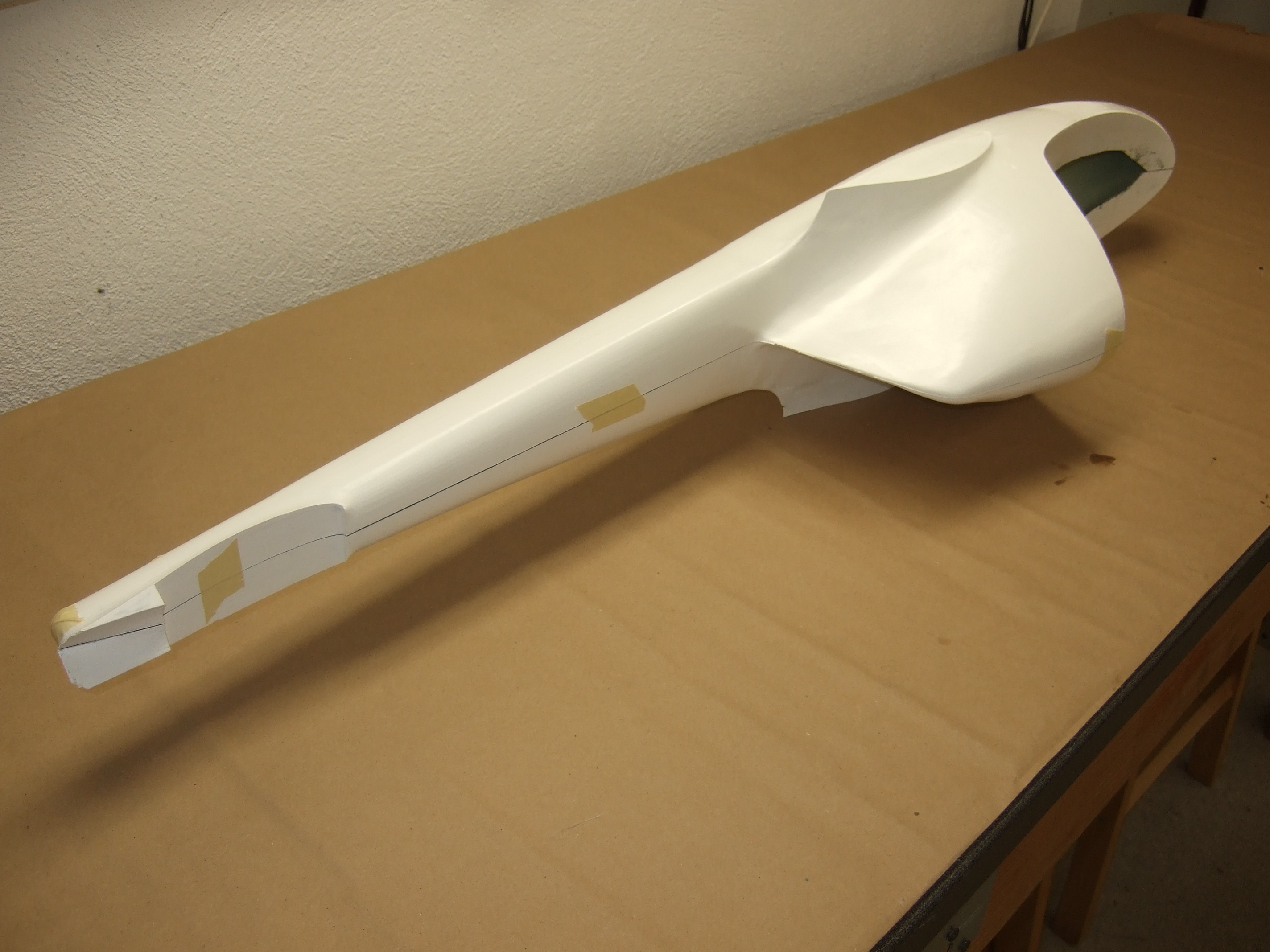
With both pieces out of the molds you can get a first impression what the fuselage will look like. In these pictures, the PVA is already washed and you can see the white gel coat.
The picture above shows the first (raw) cut of the cockpit frame. Later I trimmed this to before gluing both halves together.
I glued the halves together in 3 steps:
1. tail boom
2. upper pot
3. cockpit
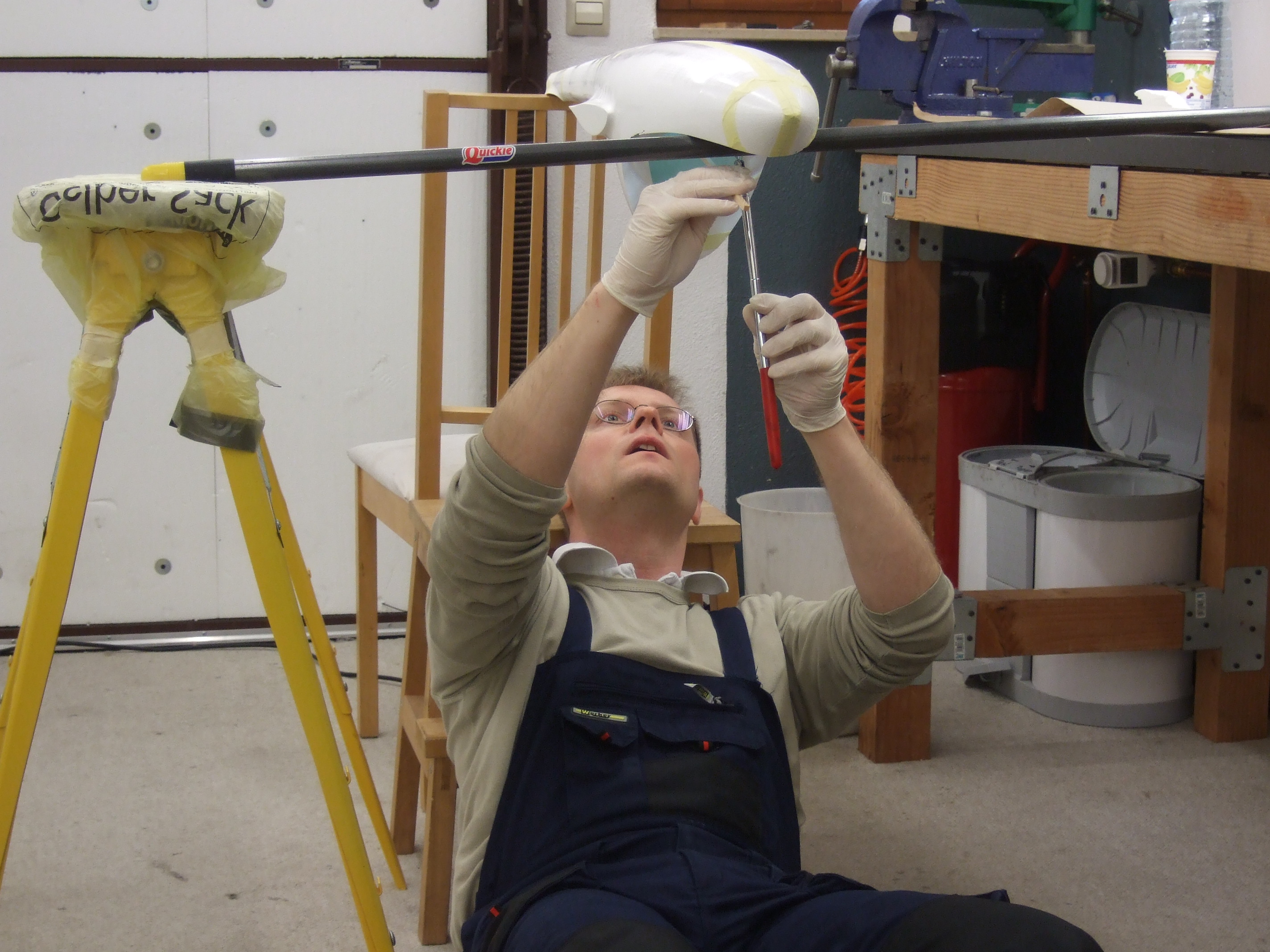
The tail boom was the most difficult section to glue. I prepared two stripes of peel ply with a layup of 50x3 cm2 fiber glass (1x X 280 g/m2, 1x || 220g/m2, 1x 280g/m2). One strip was then attached to the boom bottom of the left half and the other to the boom top of the right half. Now both halves can be joined, while one side of each strip is already in the right place. I extended the brush handle of a brush with a stick and dabbed the stripes to the fuselage shells. As can be seen I let gravity help me.
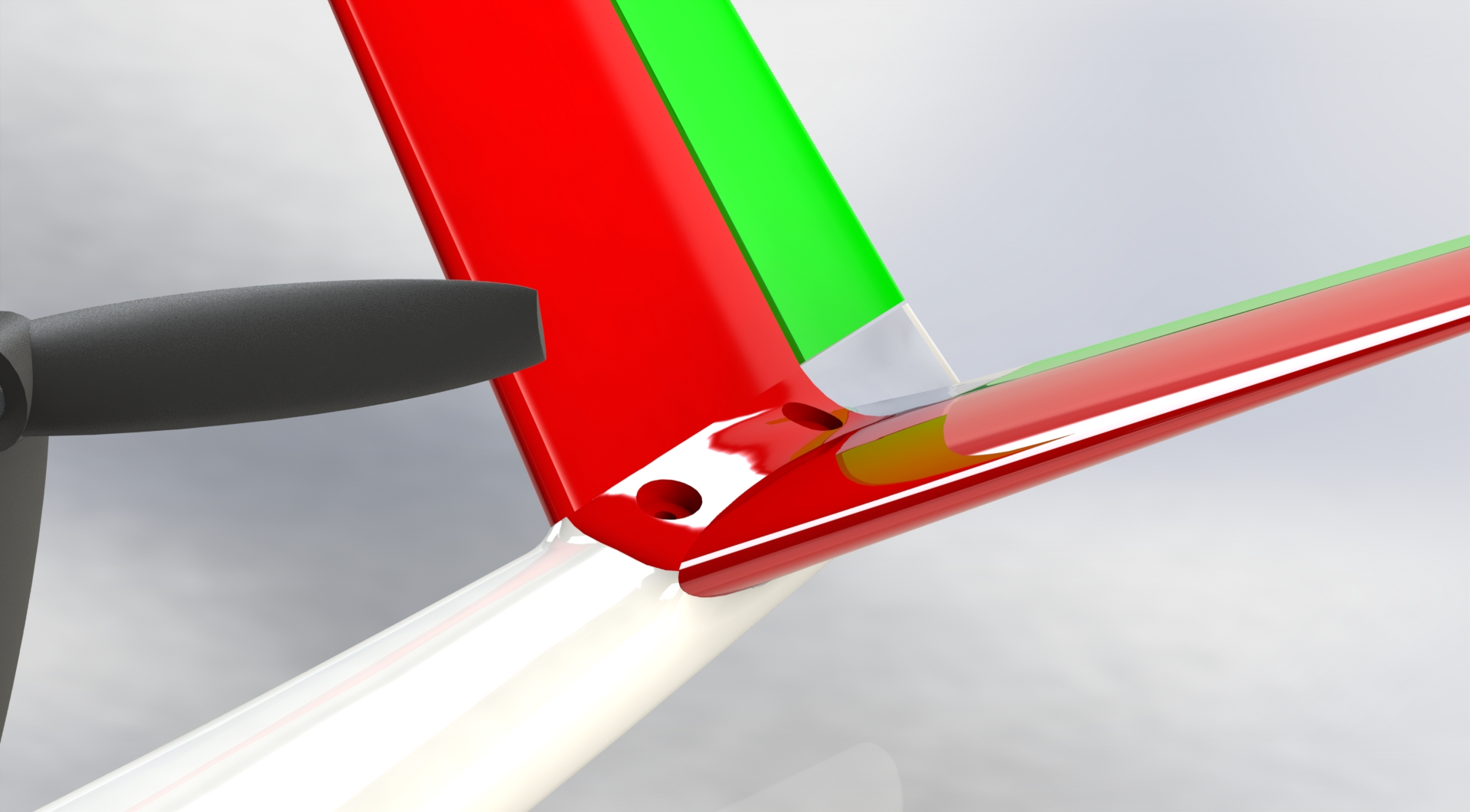
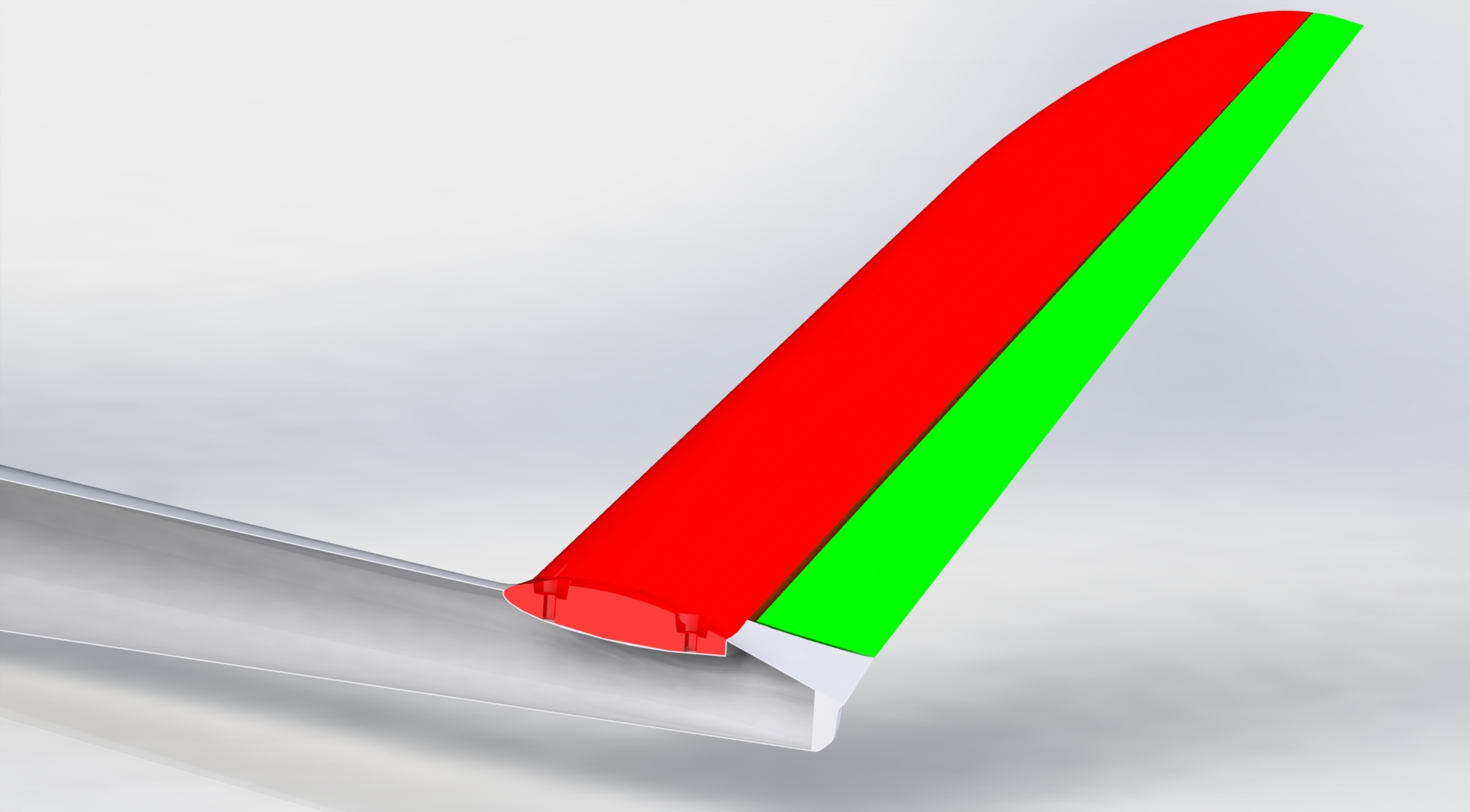
I plan to use two M5 nylon screws to fix the V-Tail to the fuselage.
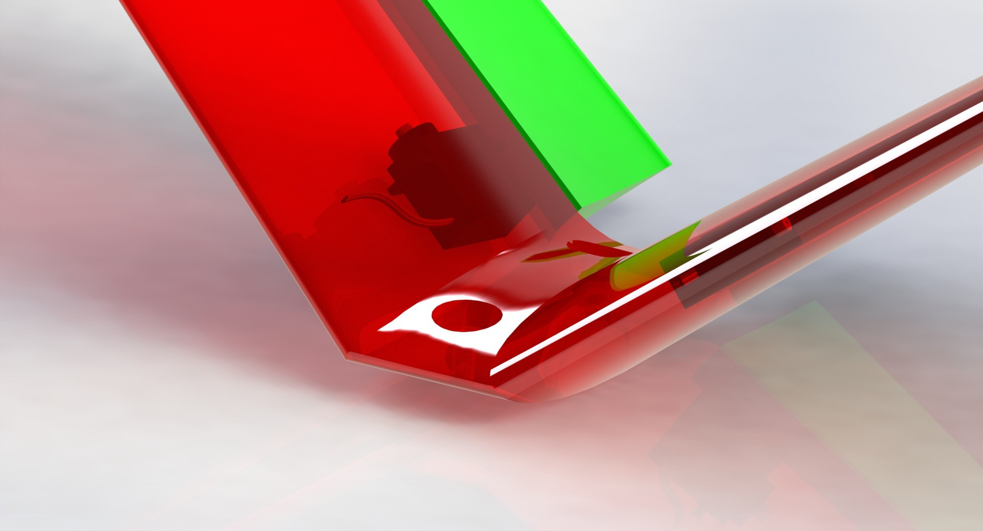
I plan to glue the servos directly into the V-Tail half's before gluing them together. This places them there permanently and an exchange would mean a lot of effort. On the other hand this solution is simple and light weight.
The video show the position in detail.
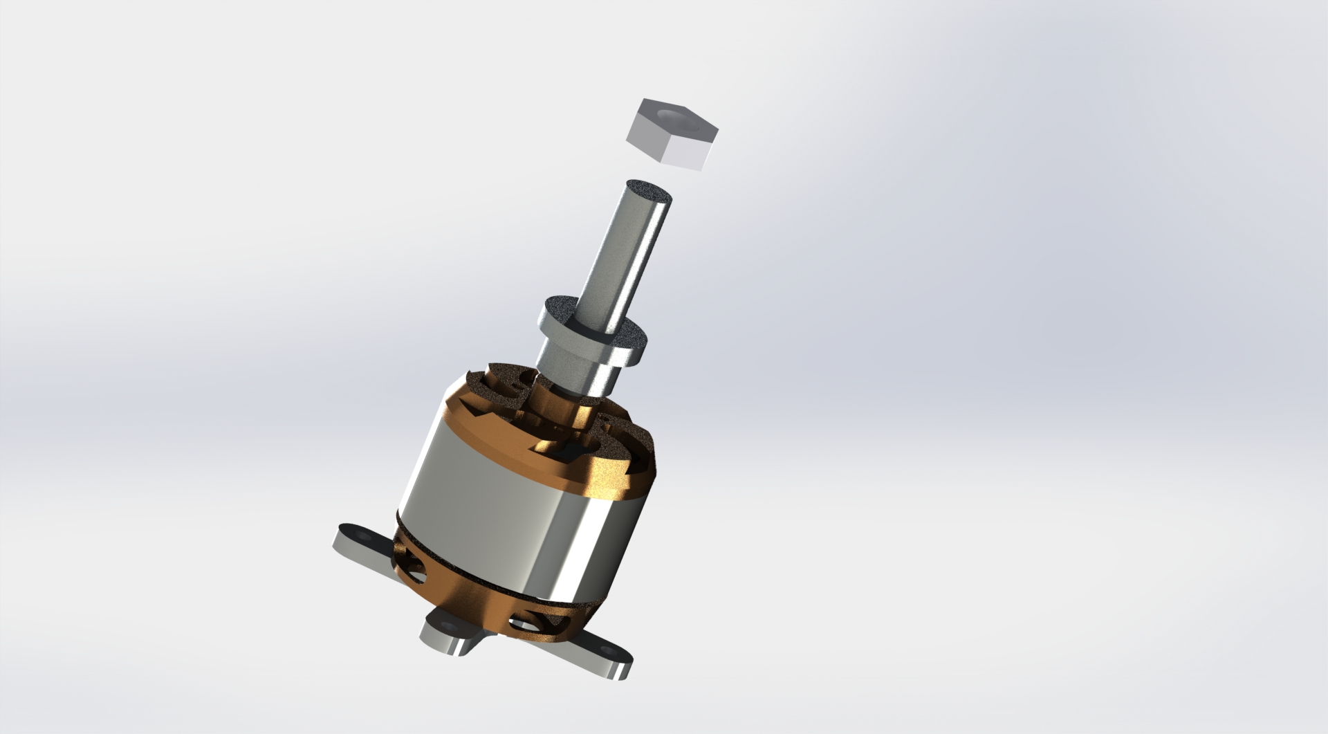
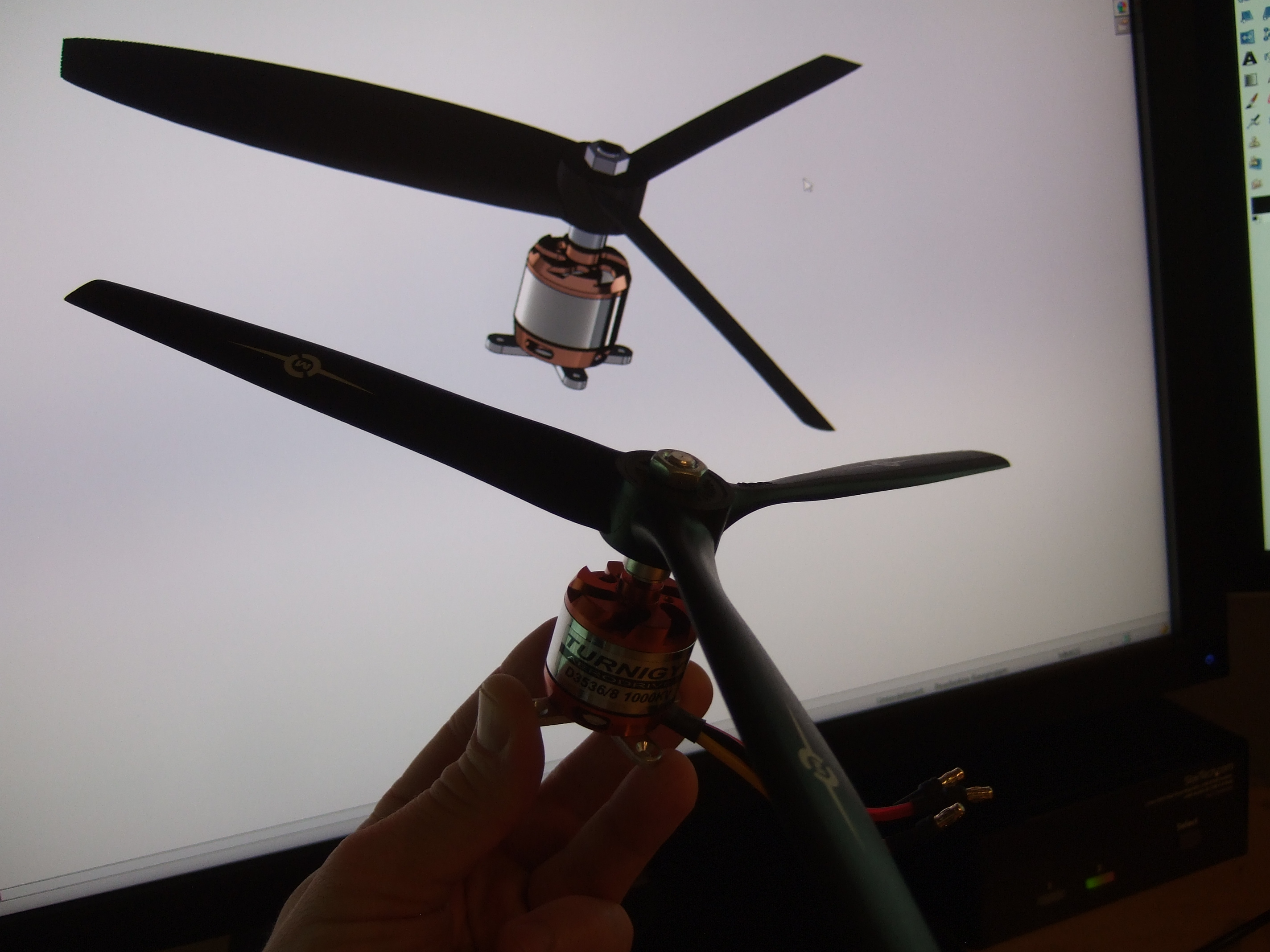
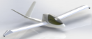
As for the motor, I decided to go for a power of 400 W and picked a Turnigy D3536. This motor is cheap and powerful for its weight. I did a 3D model of it for the propulsion system design.
Since I will use the Woodcomp Winglet 136 propeller for the J5-Mako the diameter of the propeller is set to 1,36m. For the 25% RC model this means that the propeller has to have 34 cm diameter. In addition, the Hirth F23 already sets the spin direction. Therefore I picked the "Master Airscrew MA.3B 13x60R01" which is designed and manufactured in California :-) As can be seen in the picture above I also did a model of this propeller.
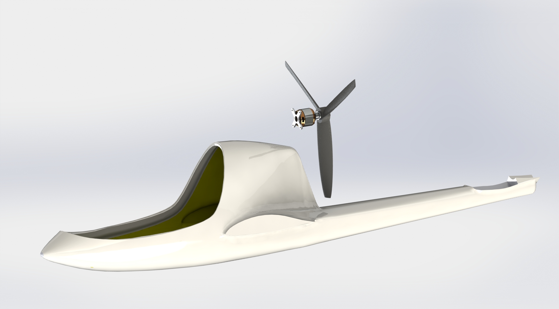
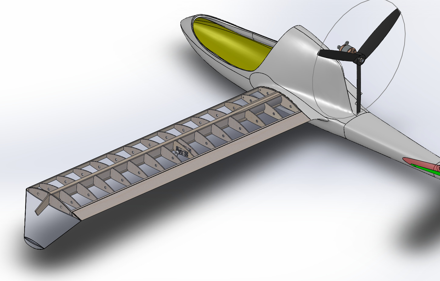
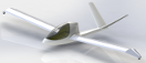
Looking at the assembly of the fuselage/motor/propeller you could think that the propeller is way to large. But the J5-Marko will fly with a Hirth-F23 engine and this engine with it's belt drive will eat up all the space between the fuselage and the propeller center. So the propeller is OK, it's just that the electric motor is really tiny. The large propeller is needed for the J5-Marko to get the 50 hp of the Hirth F23 transferred into the air.
While the fuselage is made out of fiber glass, I decided to go for a classic balsa construction for the wing. I use glass/carbon tube wing connectors from R-G and 2 carbon 10 x 1 mm2 carbon rods for the spar. On the carbon rods for the spar I will glue 1mm ply wood on the inside and 1mm Balsa on the outside. This way the rod can glued into the wing like a wooden strip. Only the wing connectors and the spar rods will stay in fiber glass/epoxy.
The small outer wings with the wheel house will be made in fiber glass, using a 3D printed mold.
To be continued...
Impressum, Disclaimer & Datenschutz
![]()