German
Mid fuselage copy
Since I have to design and test the propulsion system from scratch, I need to build a MockUp of the mid fuselage section. This is especially necessary because the exhaust system lives inside the fuselage! I belief that it is a good idea to figure out all the thermal and vibration problems at the ground and not while being in flight.
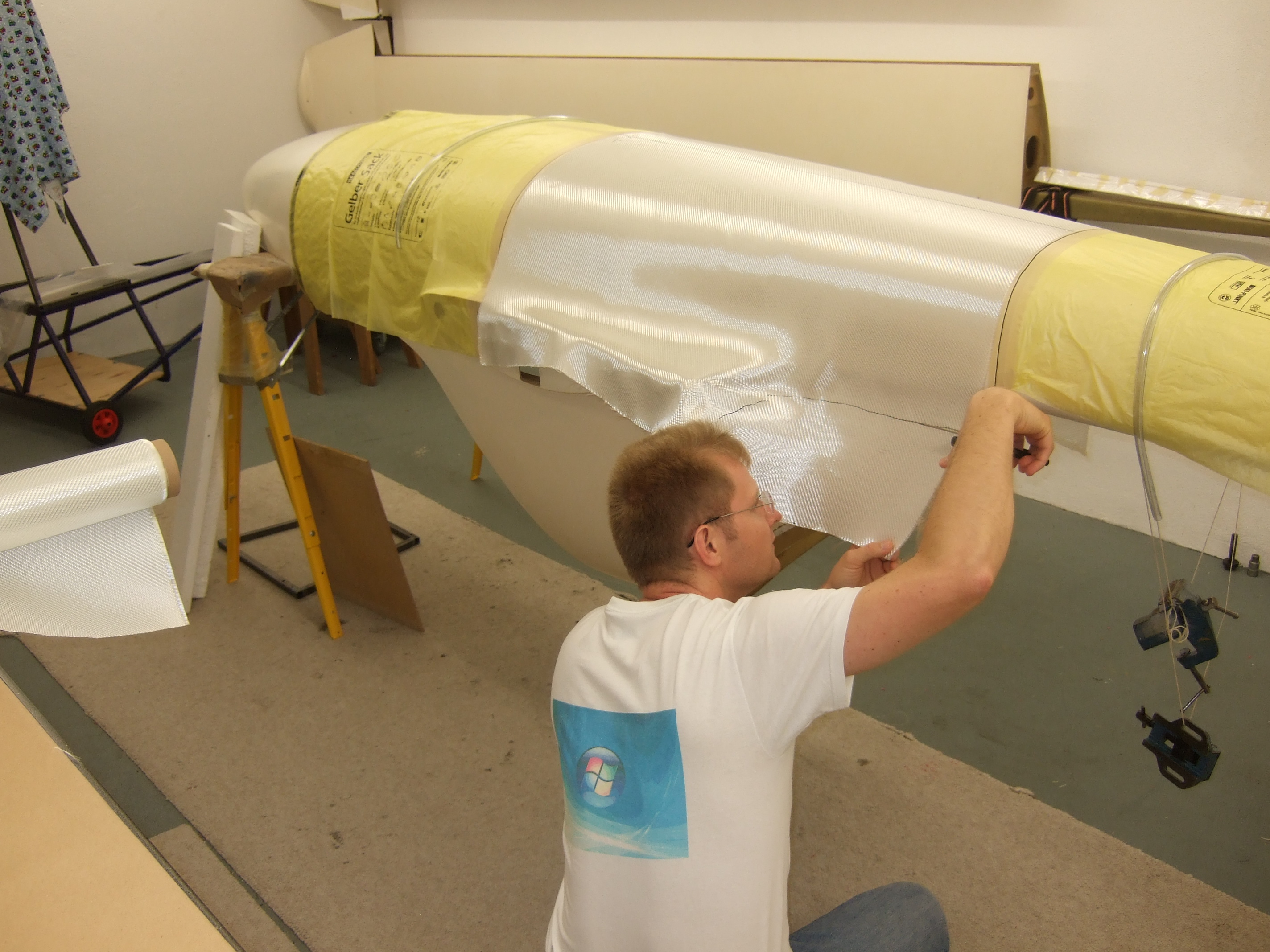 cutting fiber glass (bottom side)
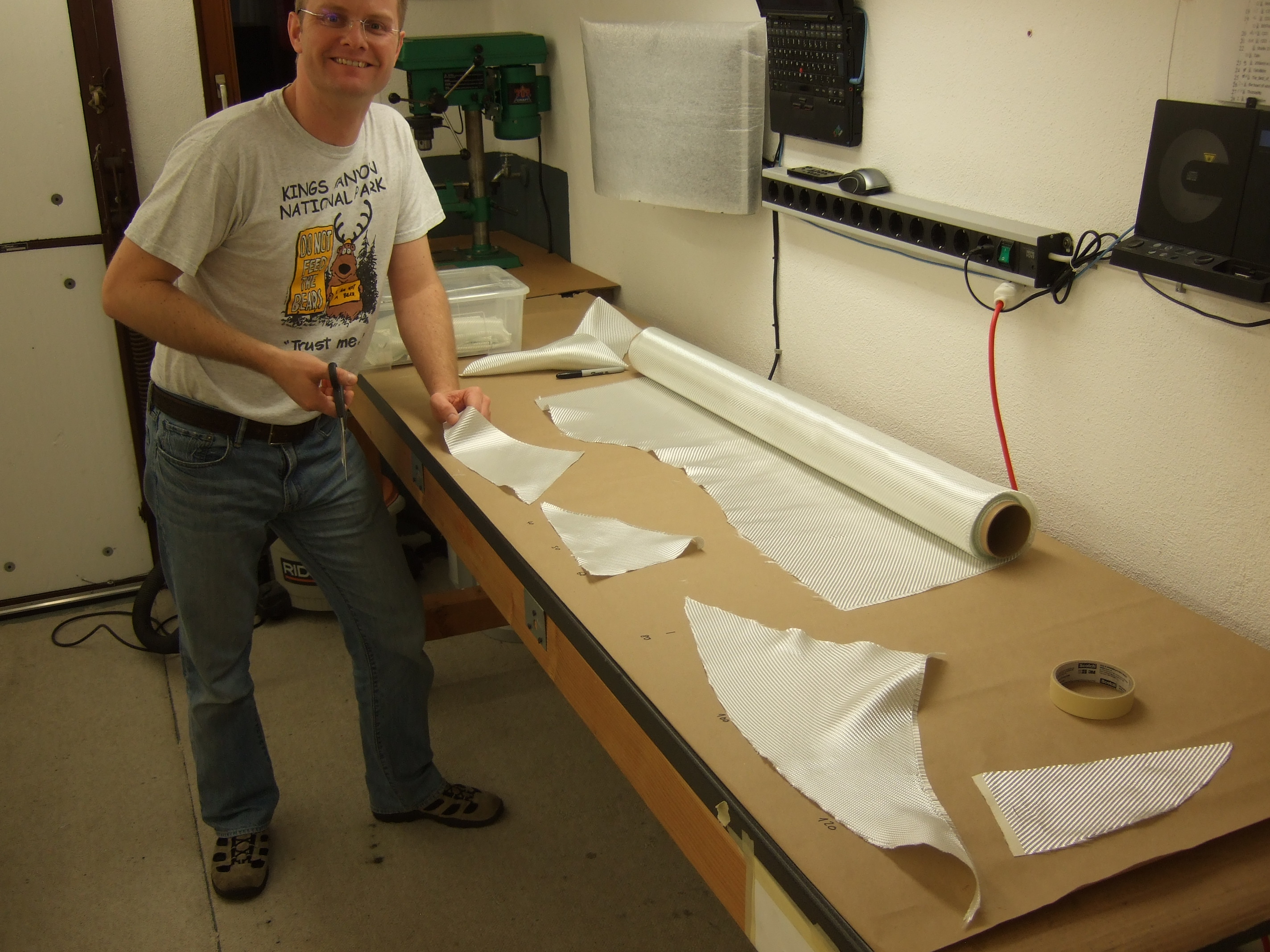
I decided to divide the mid fuselage into 3 sections and to glue them together. In this picture I'm cutting fiber glass for the bottom section.
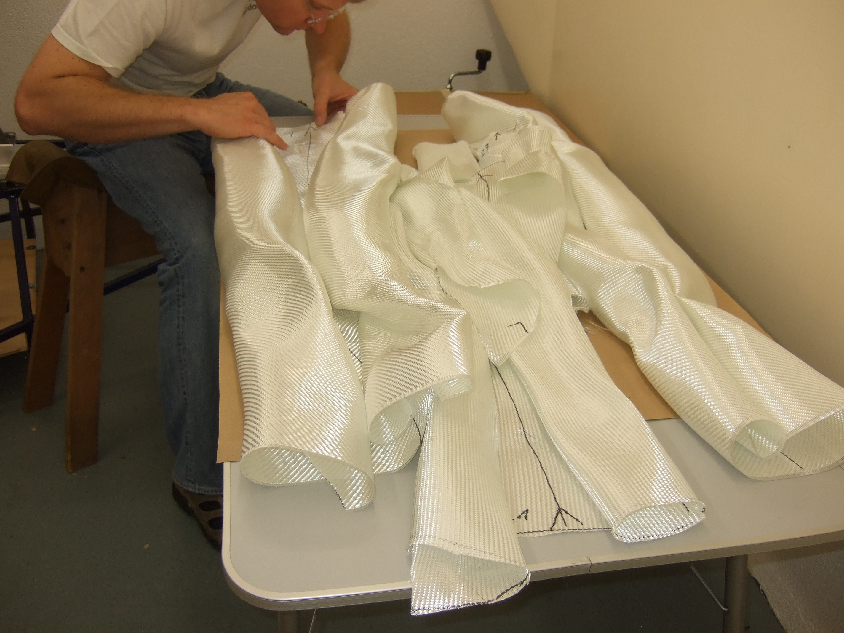
The cut fiber glass is ready to be
laid up. As always it's important to prepare everything in order to
have a smooth lamination process.
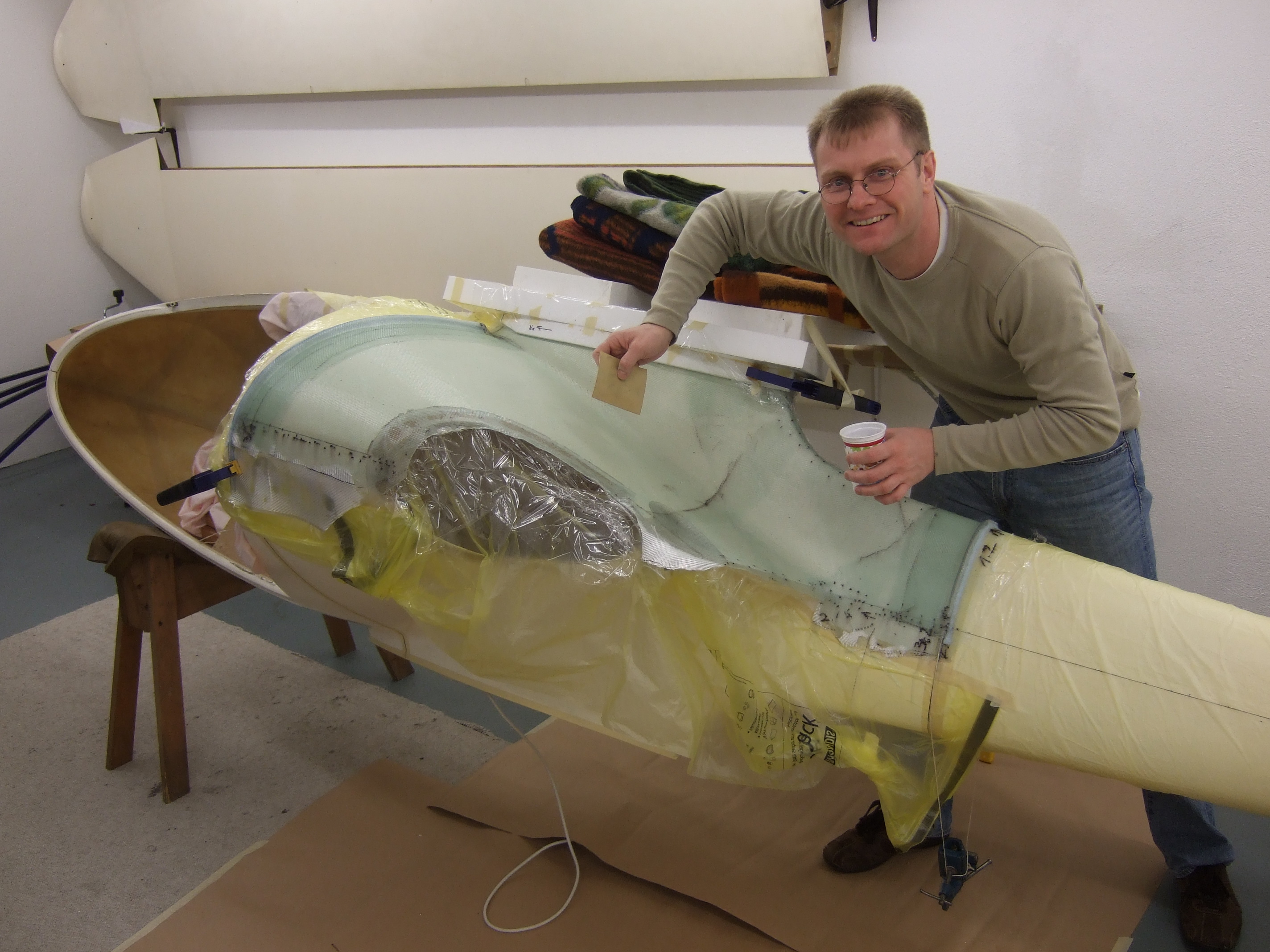
Since the inner surface quality isn't critical I used cling film as release agent. Two layers do the job and provide sufficient release reliability. Sprayed water provide the adhesion needed between the fuselage and the film for maintaining the shape. I decided for this method in order to not have to use wax or some similar release agent in order to remove the risk to contaminate a future bonding area.
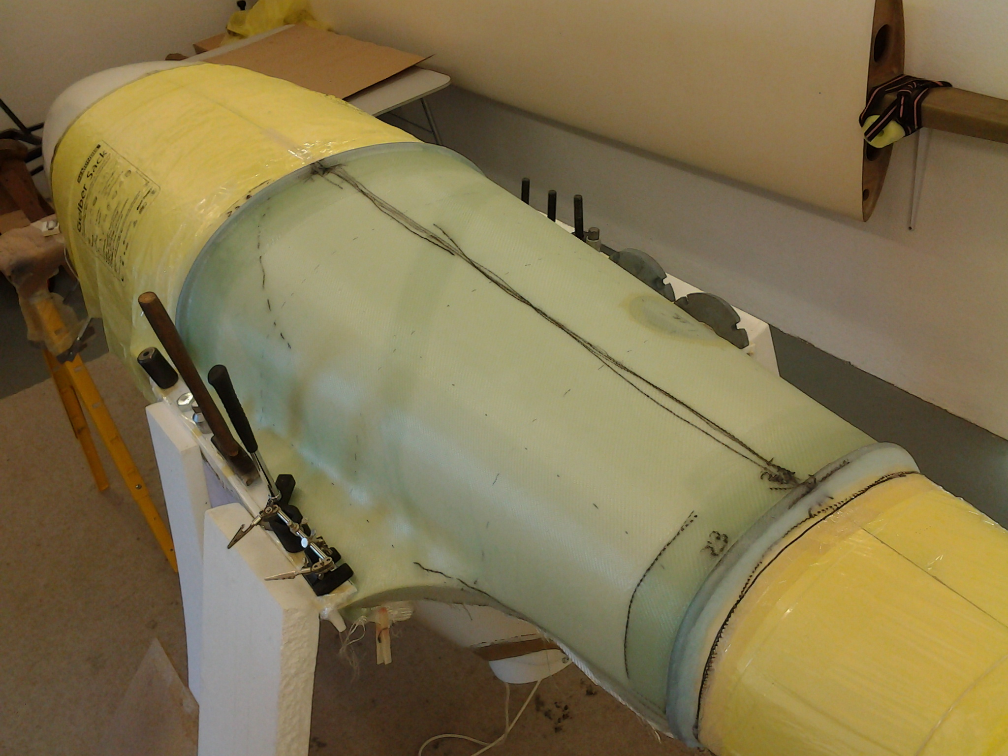
One interesting detail are the tube bulkheads at the front and rear ends (click on the picture for higher resolution). What I did is the following:
- a tube gets laid into the layer stack
- a couple extra layers around the tube form a bulkhead (simple but efficient)
- after the release the shell holds it's shape because of the tubular bulkheads
- a string going through the tube is pressing the layers to the mold while curing
After the bottom and right side, the left side is due. The whole thing isn't complicate, but all the steps take their time.
Cutting fiber glass is a bit like shaping the wood for an wood airplane, just that it's easier :-)
The J-5 cockpit is pretty tall for its otherwise small size.
After all 3rds were build and sanded
I tacked them together using one layer of fiber glass. While curing,
masking tape kept the parts in the correct position (still being on the
fuselage). I left the area in front of the spar out in order to have
the chance to slide the whole thing backwards from the fuselage. In a
second step I laid up several layers from the inside of the part
borders and also installed two mini bulkhead in the wing areas using a
conticell sandwich.
This scissors was previously used exclusively for fabric (covering aircraft). Since I don't plan to build and cover any wooden aircraft anymore this scissors gets assigned to peel ply duty.
Speaking of resin I switched from L285 to L385.
My whole life I was using L285 and really liked it. But using L385
especially with the slow H387 feels to me working even better than H287
with L285. Referring the datasheet L385 is even less harmful than L285
(L385 is not labeled toxic, important for shipping costs!).
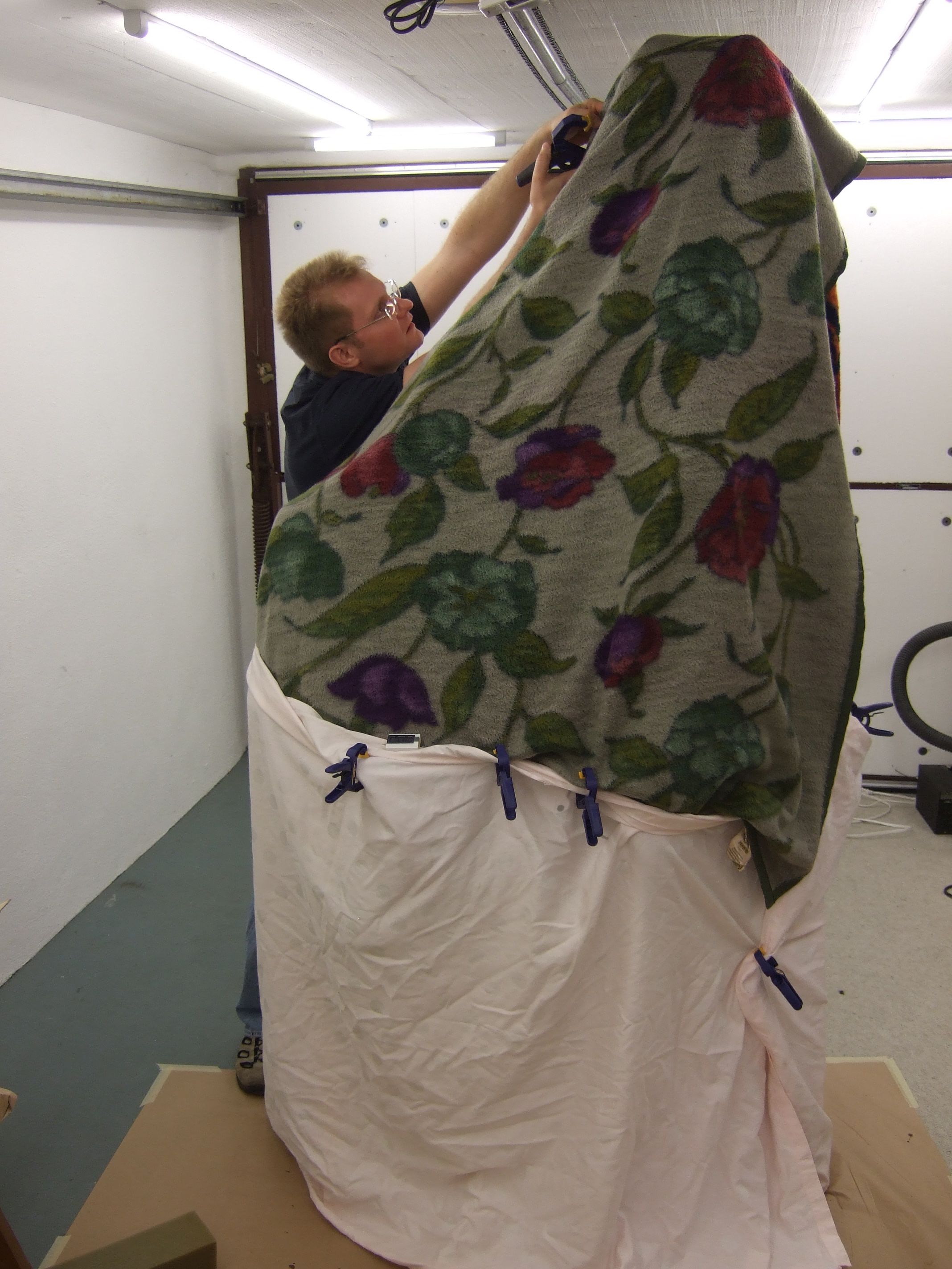
Since the parts were pretty big I decided to cure with the slow hardener. As always and especially with the slow hardener post curing is obligatory! The 3rds were already post cured on the fuselage, but also after gluing them together, post curing had to be applied. This time I didn't build a post cure tent, but simply covered the whole thing with blankets.
These days you can buy small size and cheap temperature logger. This way you can check whether you reached the temperature goal for the post cure process.
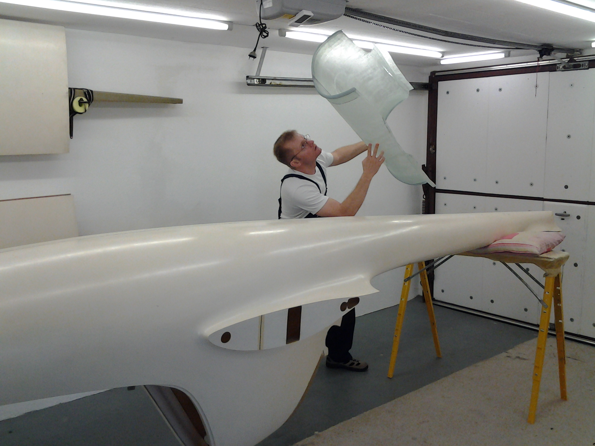
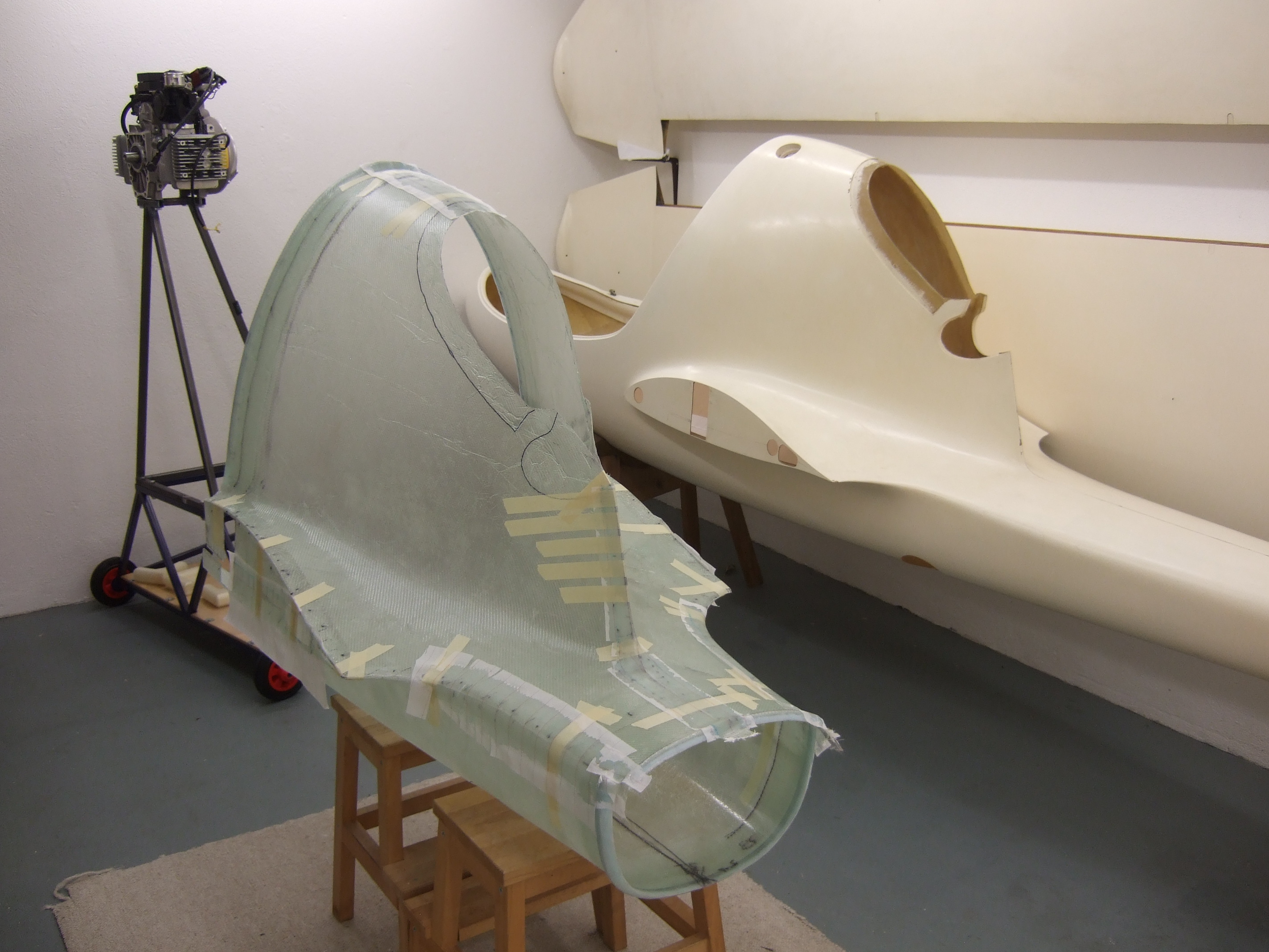
Bonded together you can now see the tube bulkheads in the front and rear. These tube bulkheads provide already some stiffness to the mockup shell even without the real bulkheads installed.
This picture gives you a clue how the engine test setup together with the fuselage mockup will look like.
But before the fuselage mockup can be finalized I need to design the load transmission from the engine into the fuselage. This gives the chance to test the building techniques on the mockup before applying it to the flying thing.
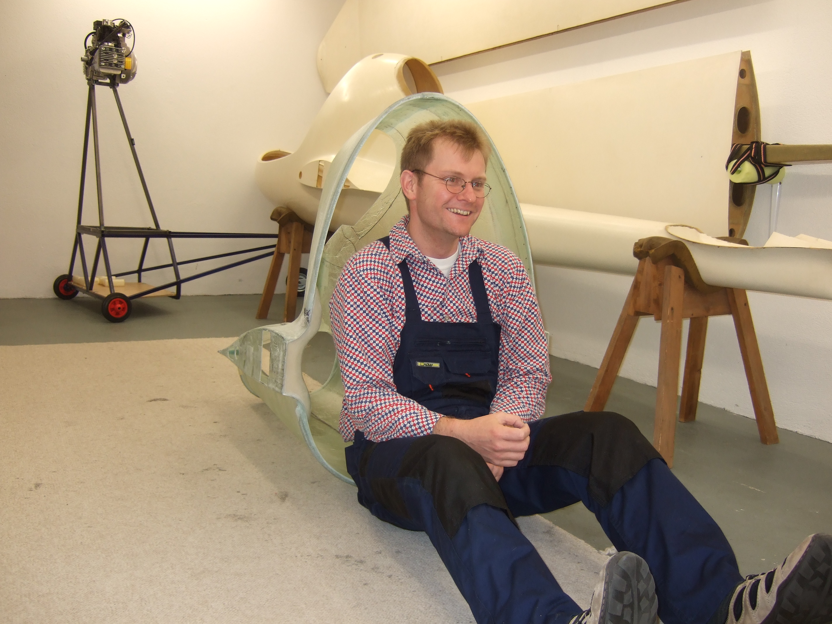
This already looks like a part of an airplane (-: Just for fun I took a seat :-)
The next step is to laser scan the fuselage
shell, so that I can generate a 3D model of the J-5. This is needed to
design the engine setup including it's exhaust system which lifes
inside the fuselage. So the handyman now needs to get some 3D CAD
computer work done before going back into the workshop.
Impressum, Disclaimer & Datenschutz
 (right) side layup
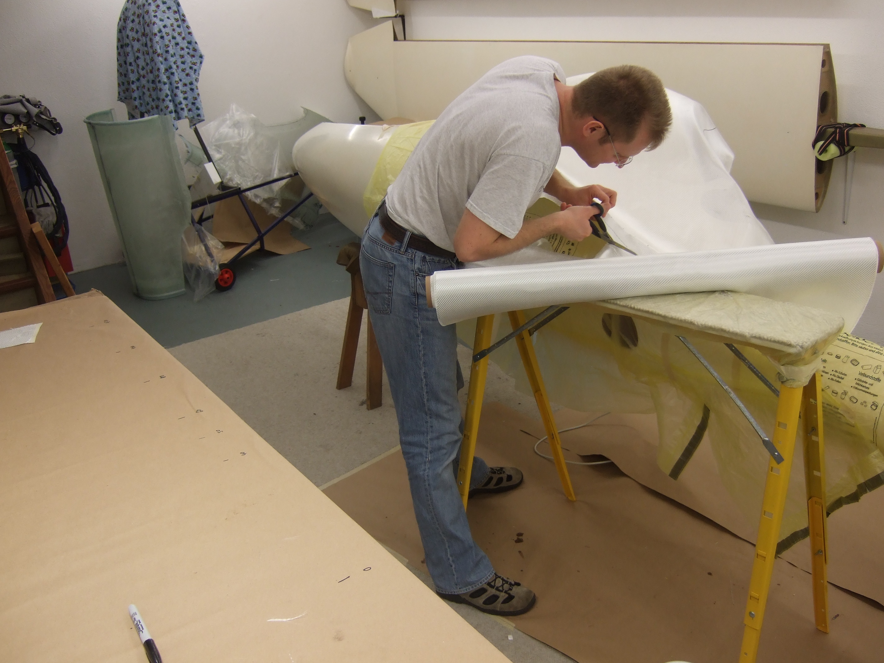
 more fiber glass
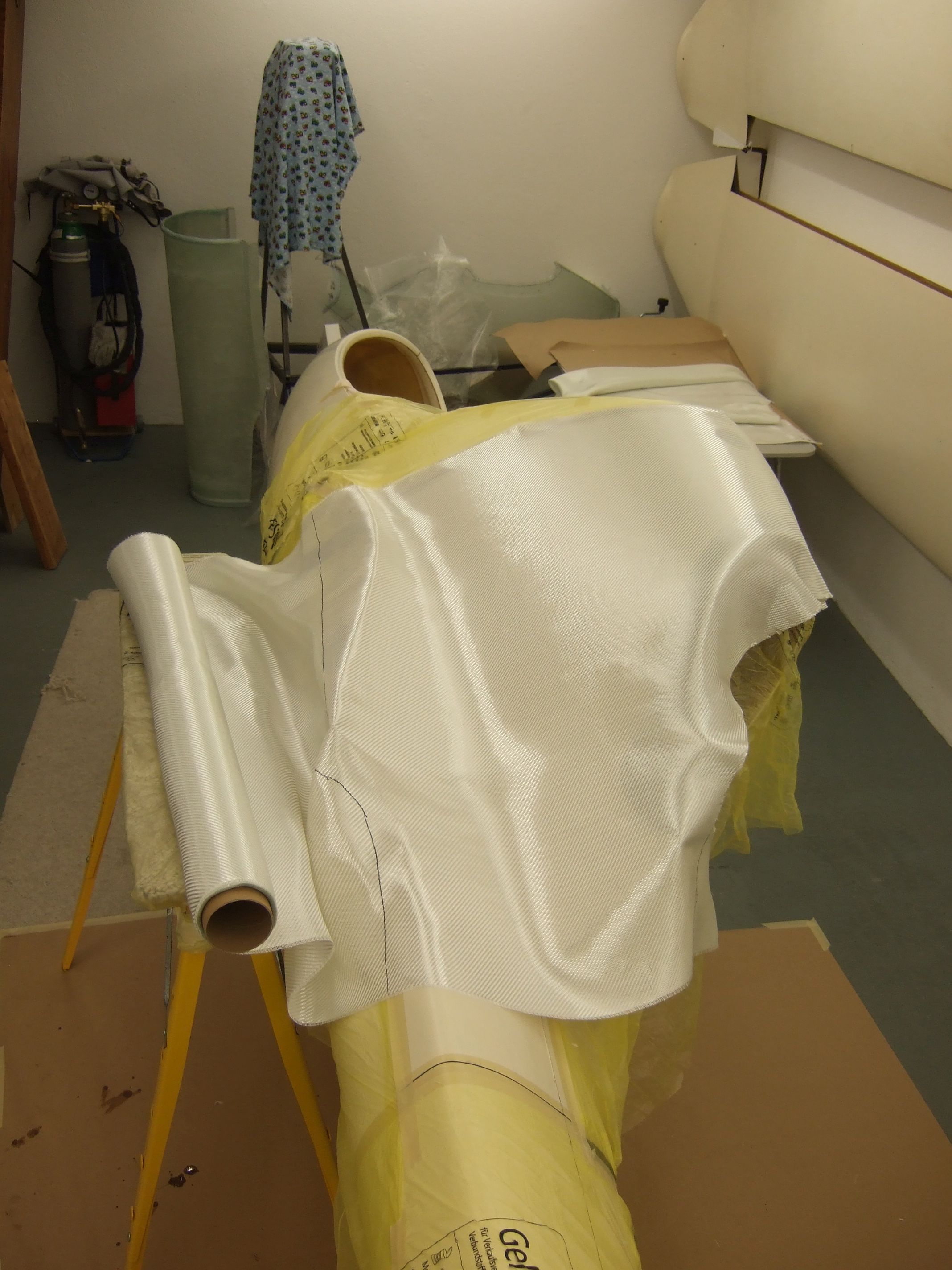
 Bottom side
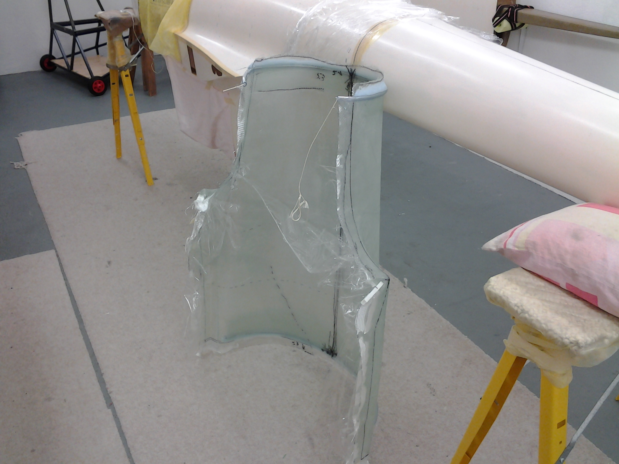
 tacking the 3rds
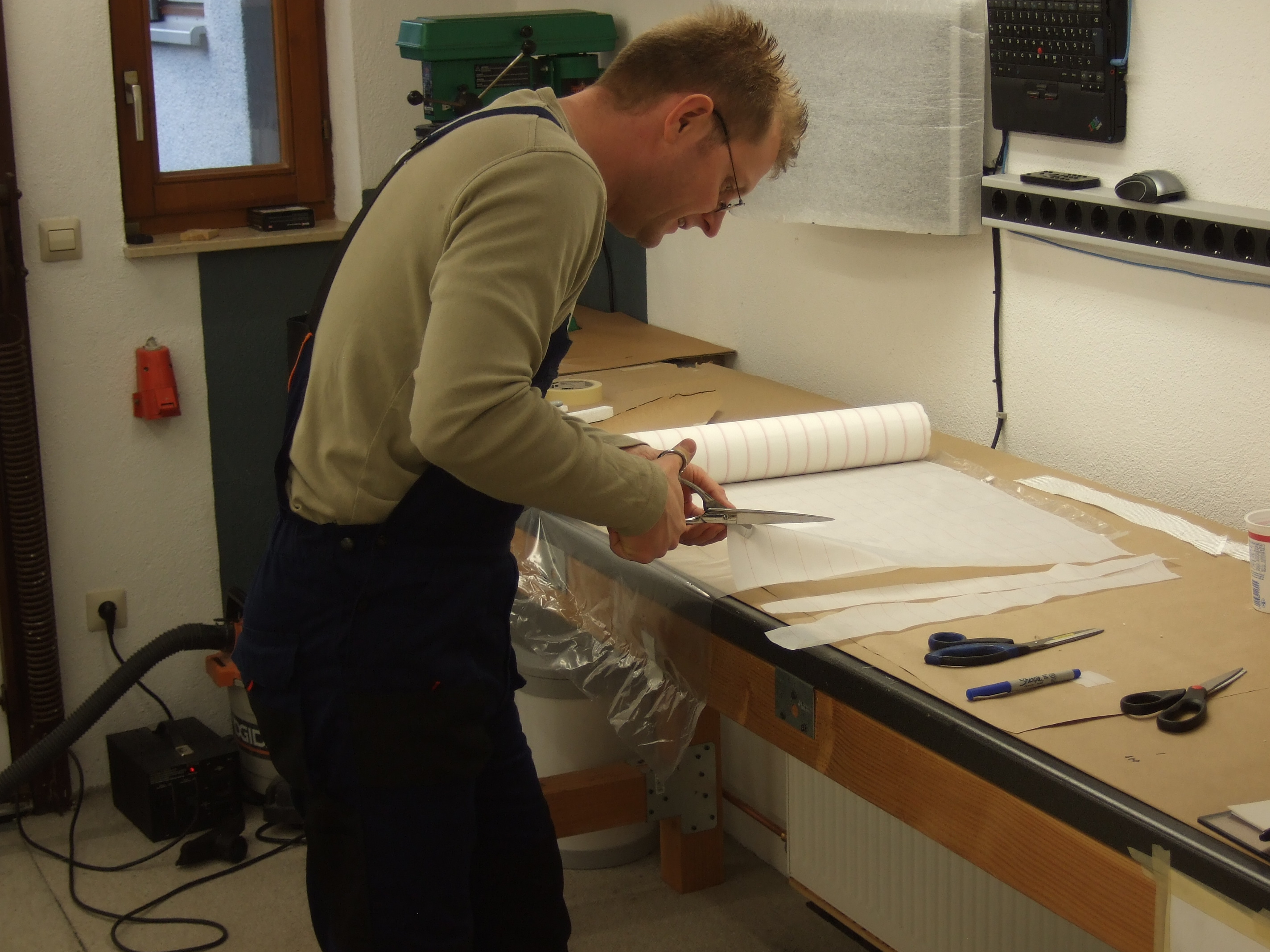
 post curing
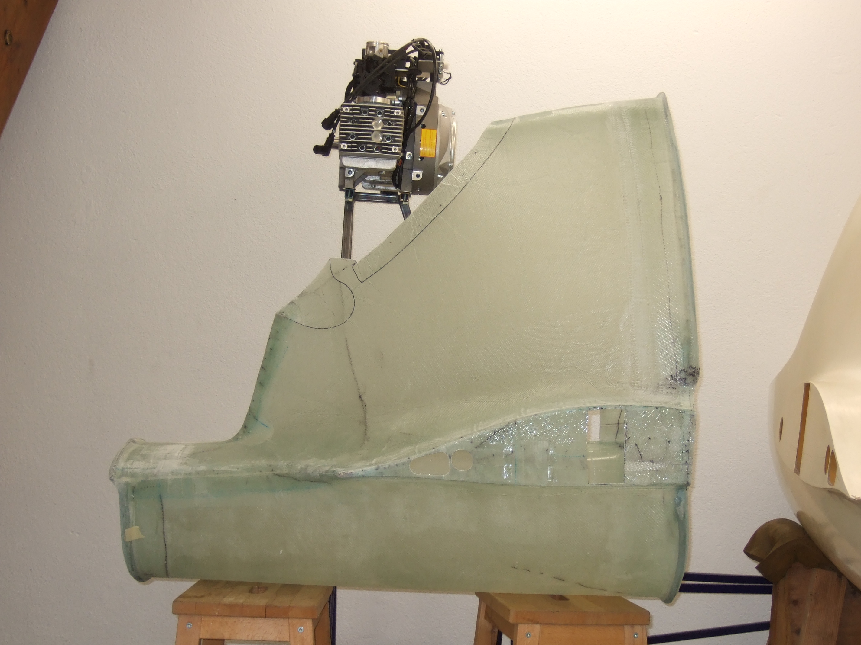 engine in the background
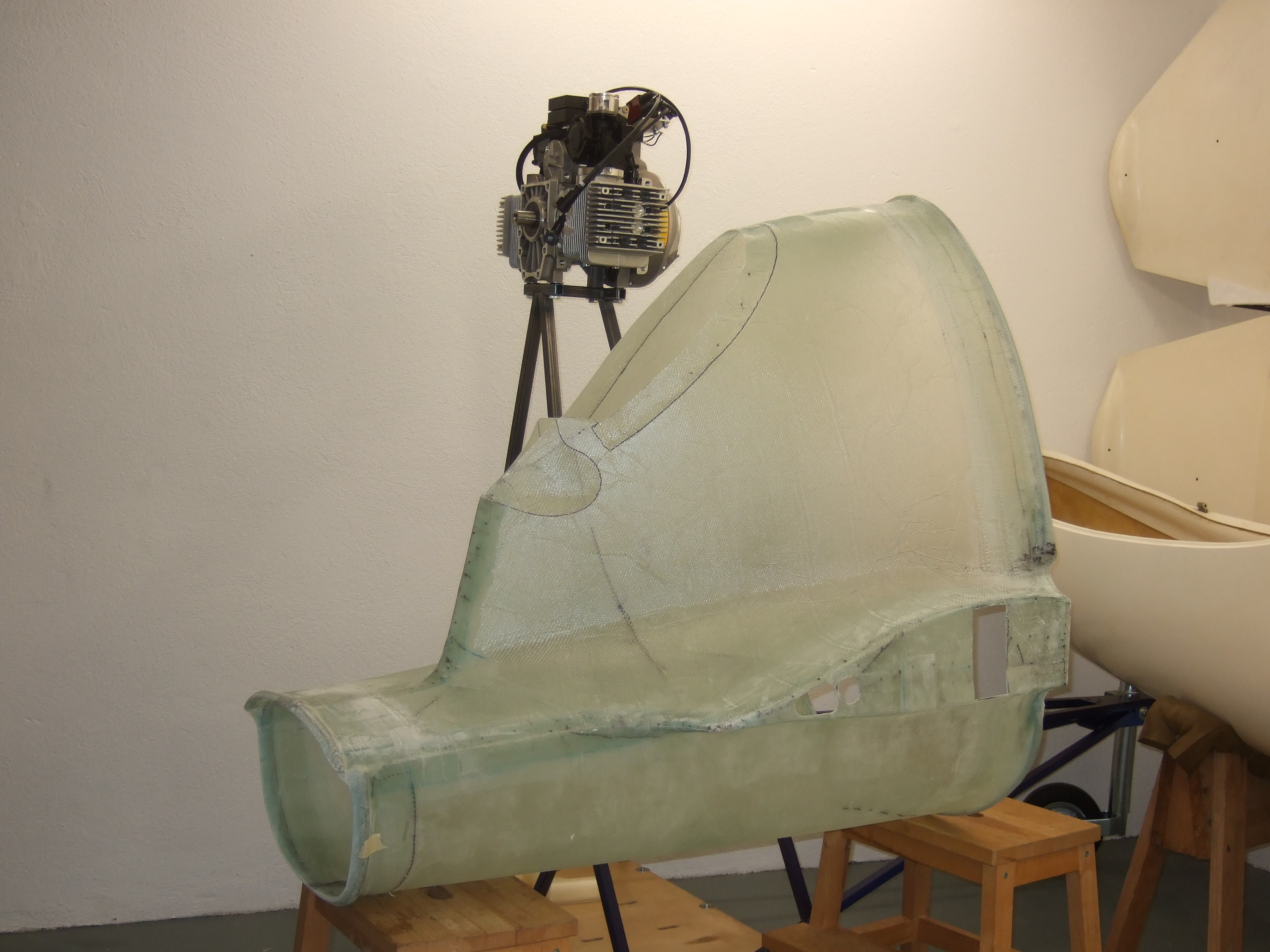
 dreaming
 J-5 Home