German
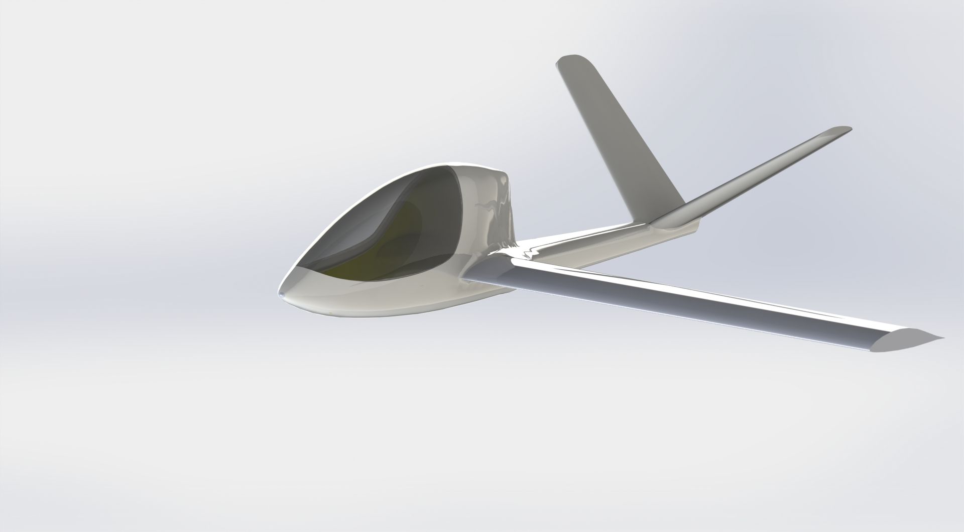
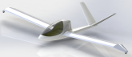
Fuselage shell 3D-Modell
With the 3D scanning of the fuselage the work wasn't done, it just started!
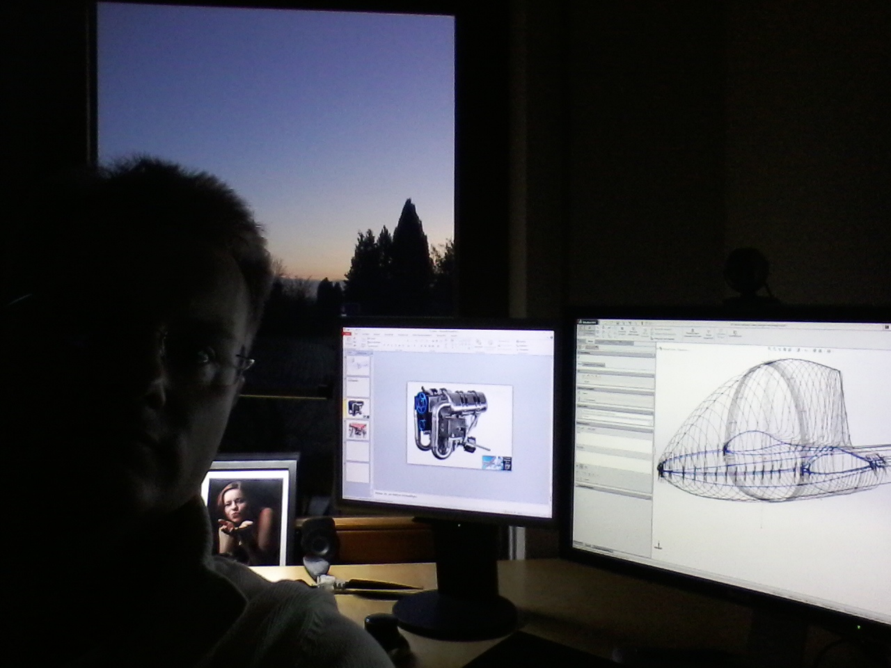
Having a family with 3 kids plus a full time job fills my day enough so that there is hardly time for myself. The only chance to work on the airplane design is the night. Since I'm often quite tired in the evening, I switched to the mornings for working on aircrafts and aircraft design. Sometimes I start before my family wakes up.
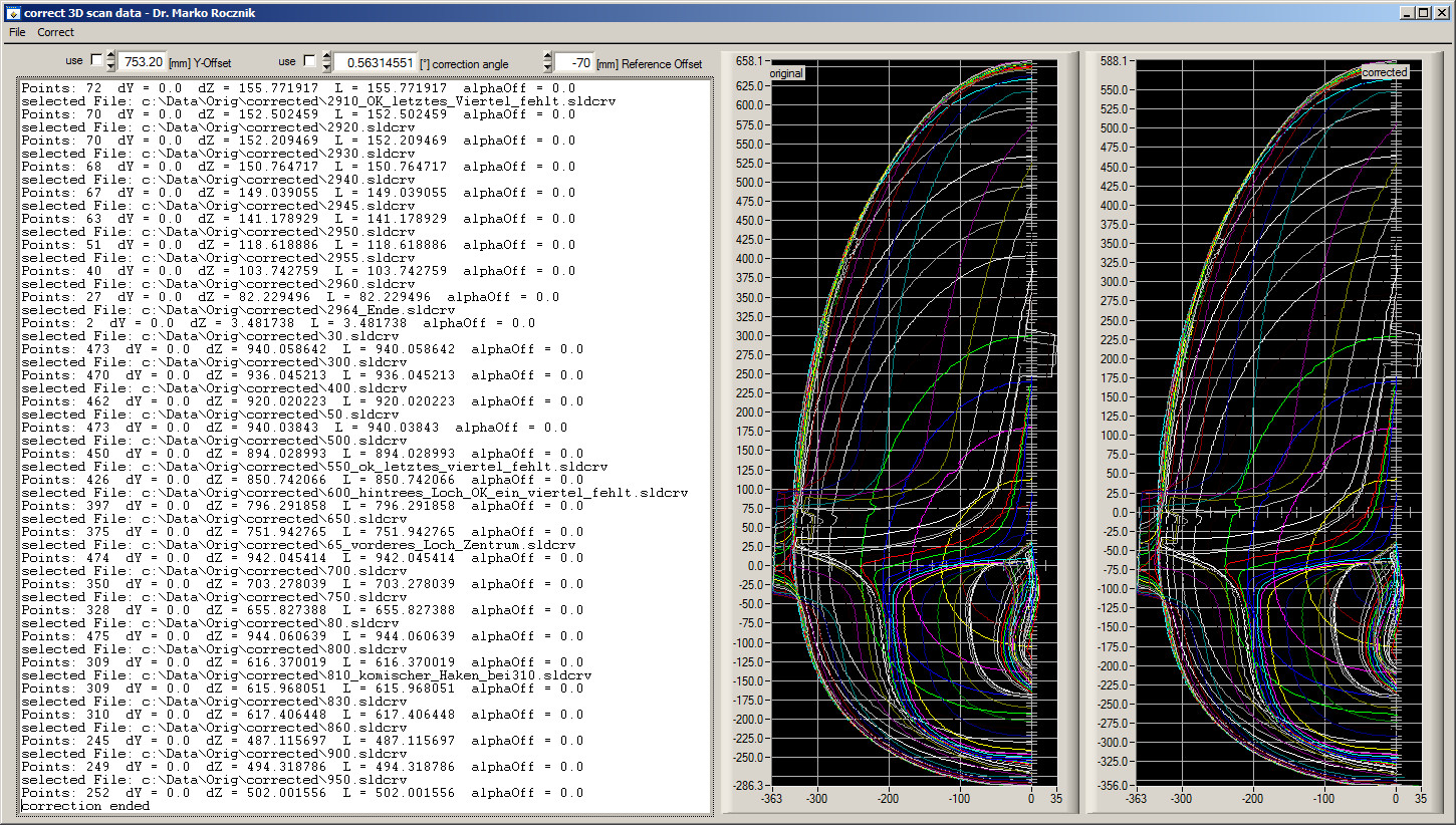
Modeling the fuselage shell started with correcting the scan data. You have seen on the previous page that I use window seal tape to mark the center line of the fuselage. This marking can be seen in the data, which enabled me to trim the start and end points. Having done this I wrote a computer program which takes this trimmed data (a whole directory) and corrects it for the height offset and rotation error (the not perfectly leveled scan object). For the later I converted the Cartesian coordinates into polar coordinates, calculated the miss angle, set the foot point to Y-zero and rotated all point with the negative miss angle so that the top point will also have the Y-coordinate zero. Finally my program computes the data back into Cartesian coordinates and saves it so that it can be read by the 3D CAD program. I wished that the CAD program would have been able to do this, but maybe this was to special.
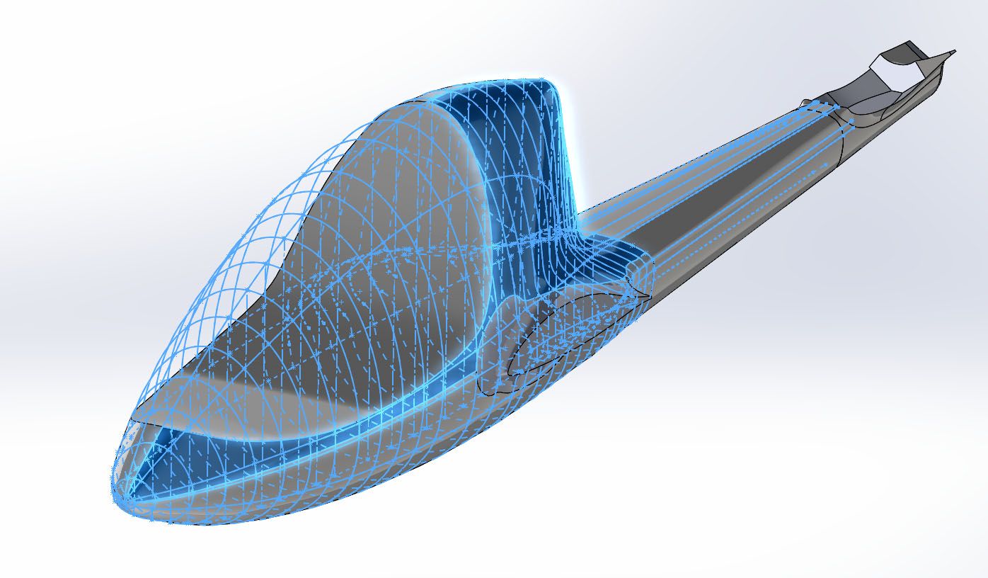
With the corrected scan data I created cross sections for every station by using as few fix points as possible for the splines. The goal was to keep the surface as smooth as possible while maintaining an error of less than 1 mm. In total there were about 100 cross sections, even if only a few of them were finally used. The problem is that you don't know which you need, until you are done. Besides these cross sections you also need guidelines for generating the 3D body. While some can be well defined by angled plains, others (in the fuselage wing area) have to be done by the designers eye and hand. The problem here was, that the used 3D CAD program is not able to mirror 3D sketches, so that this had to be done by hand (copy, modify Y-coordinates).
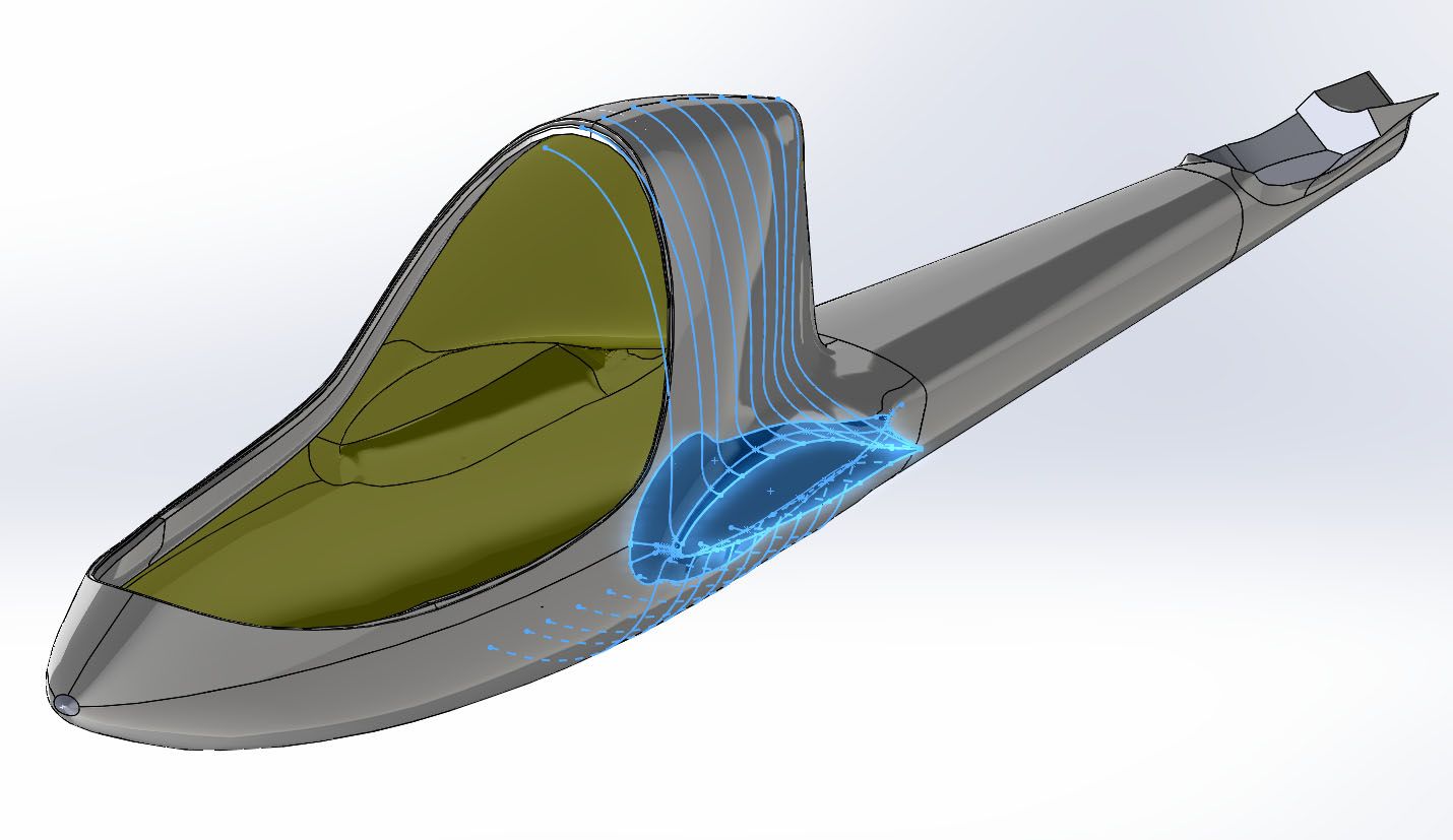
An important point in creating the fuselage shell model is the strategy of modeling. As a test balloon I tried to simply line up the cross sections and to create a solid body out of this, which to my surprise the CAD program could handle. Of cause the area around the wing/fuselage intersection wasn't all correct and so the resulting sharp edges (small diameter) prevented the wall feature from being executed correctly. So I started again from scratch by cutting off the wing connection area from the pot. This way the pot was easy to handle.
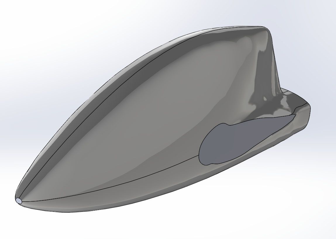
As for the wing/fuselage intersection I modeled this area separate, but not from the front to the back but from the outside to the inside and merged the bodies afterwards. This way the modeling was accurate and the wall feature went through without problems. The boom is modeled as a strait body between two cross sections.
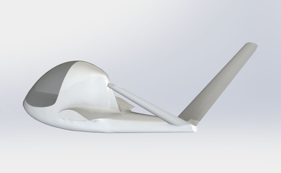
The tail section was a bit more effort to model, but with patients and the gained experience this was doable. Just remember that I'm not a mechanical but an electrical engineer!
The inside of the tail section wasn't scanned, but it was clear how it looks like: The T-Tail has to fit in. So I created a V-Tail dummy and used it to model the inner area of the tail in sufficient detail.
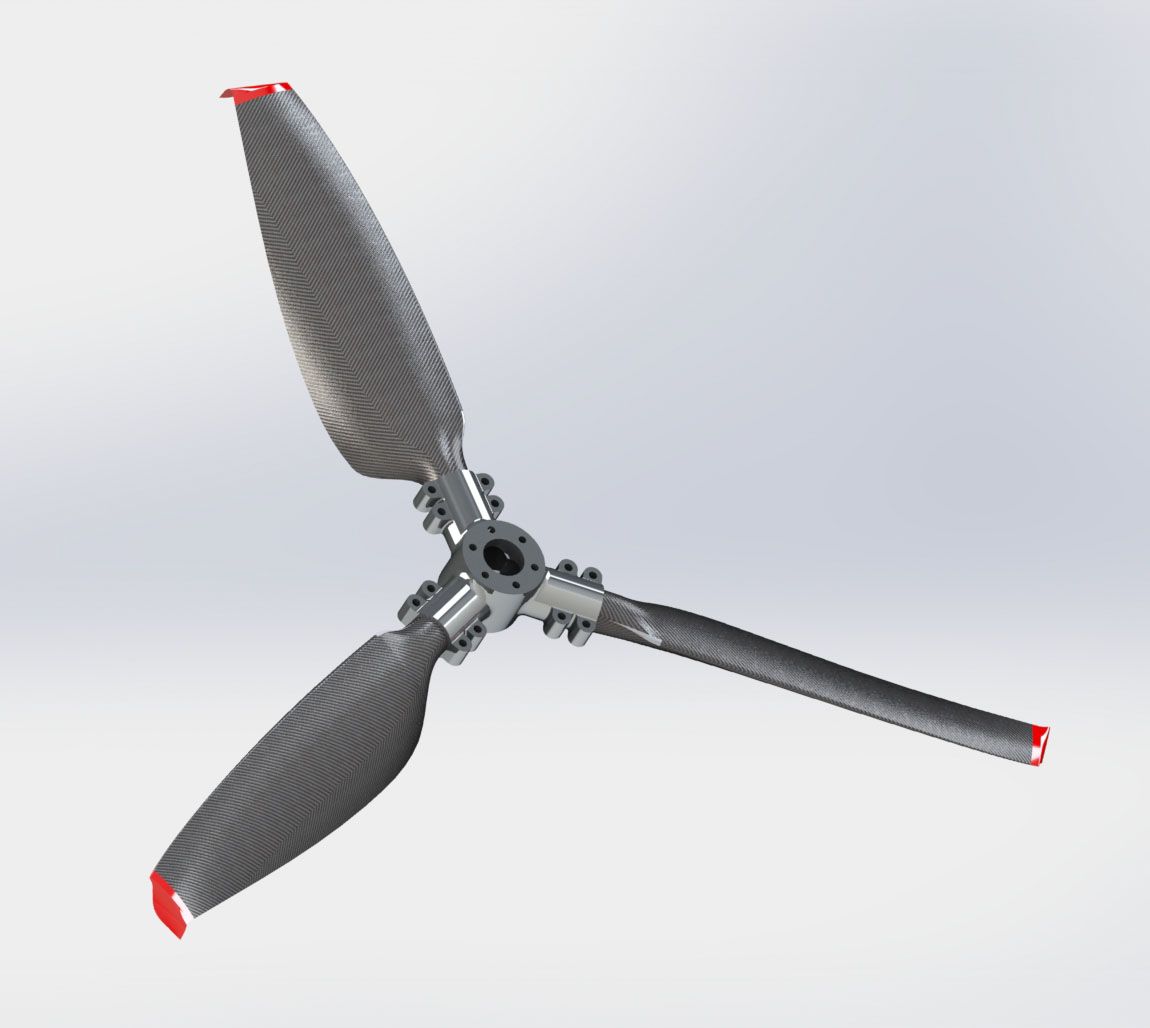
Chose the right propeller for the Hirth-F23/J5 combination isn't strait forward! With its 50 hp the engine is quite powerful and requires a big propeller to transfer this power into the air without overturning. While the common propeller diameter for the F23 is about 1.60 m, the original 0.70 m J5-propeller was way smaller! So a compromise is needed. One constrain was that I do not want to build the propeller myself, even after I got molds for it. So I was looking for the smallest propeller which can handle the Hirth-F23. The topic "propeller" is this complex, that I might write an extra page for it. Finally I choose the Woodcomp Winglet 136 . Since I had no drawings of this propeller and I do not want to buy the propeller before it is required for the test runs (10 year TBO) I had to create the propeller model from the manufacturers webpage pictures. So the dimensions are all estimated, but this is good enough for the decisions which have to be made.
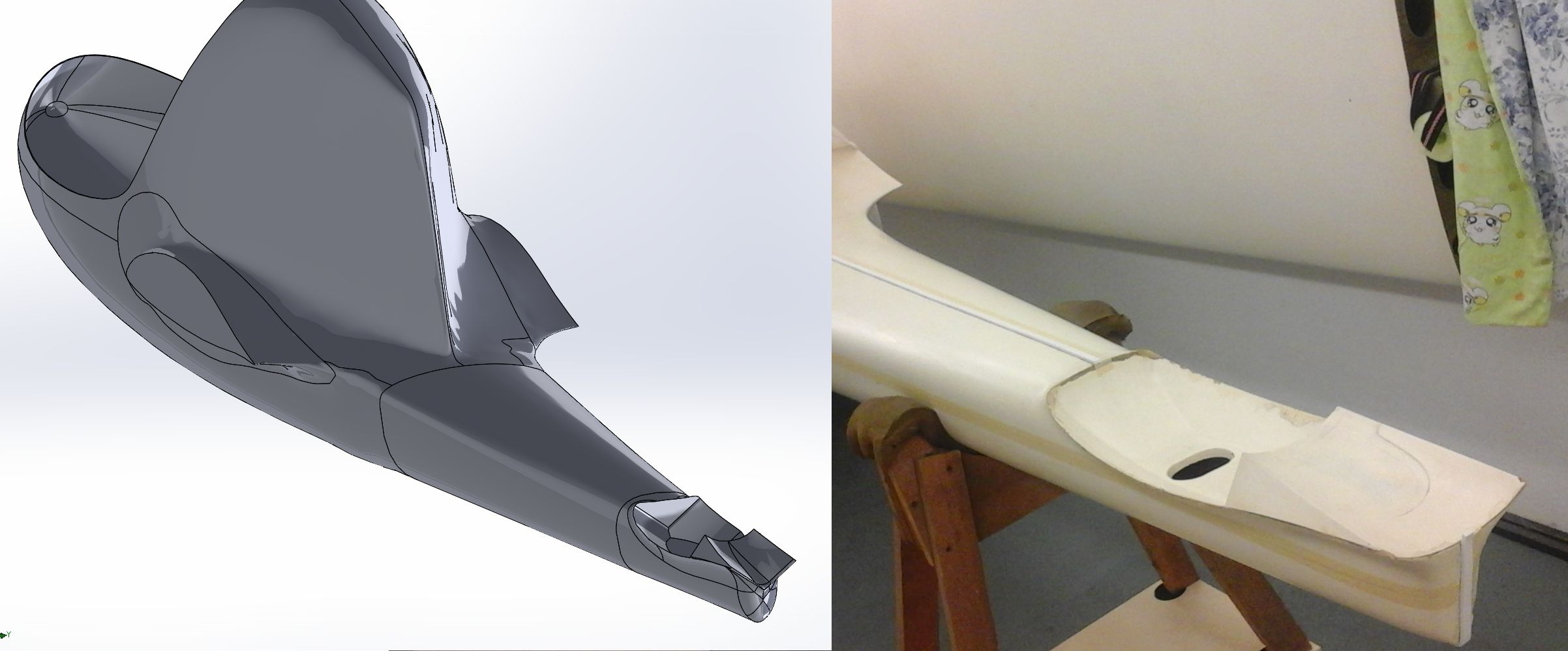
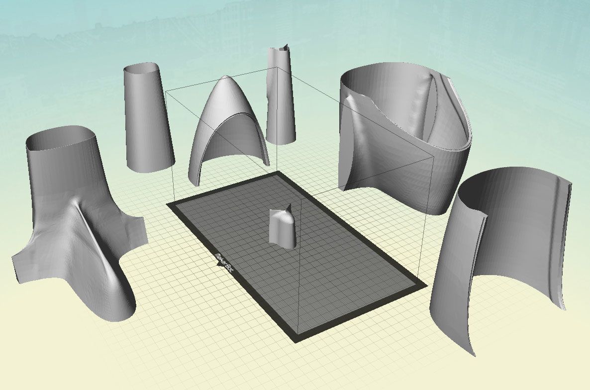
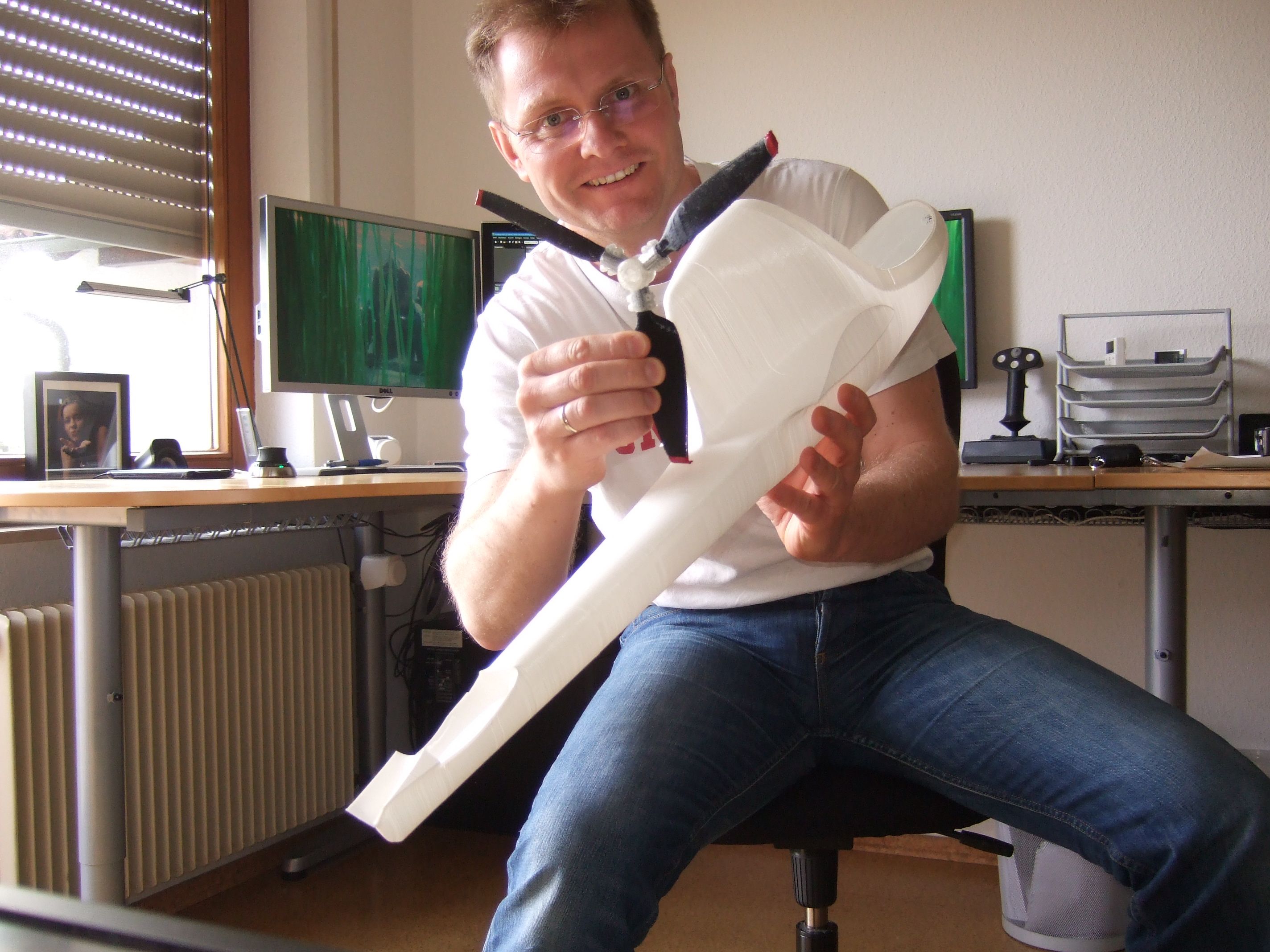
Since I now have a model of the fuselage shell, I did a 20% scale test print on a 3D printer. I have cut the model into pieces the print room could handle and printed the shell just the way it was. I wasn't expecting much, since clearly only one layer was printed (at least 2 layers would have been required).
The result wasn't this bad at all. Of cause the walls have the consistence of a yogurt cup, but glued together with instant glue it is stiff enough so that you can touch it. Well - it was an interesting experiment. I might made a LED lamp out of it ;-)
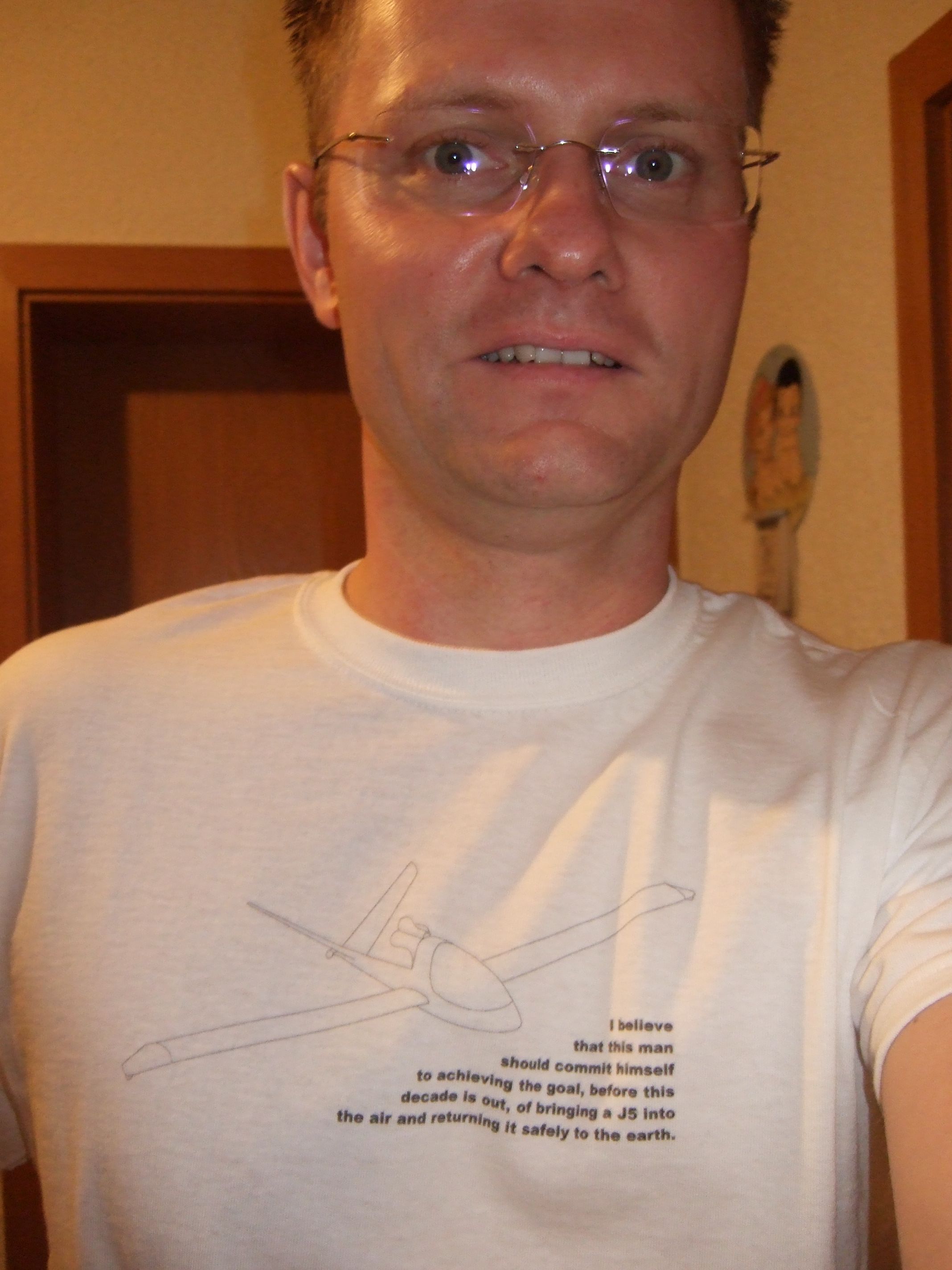
The design work is progressing slowly since my normal life is quite demanding right now. To push things a little bit I designed this motivation T-shirt. The sharp eye will recognize a modification of the Kennedy speech which ignited the Apollo moon program.
Now that the fuselage shell is done one more thing is needed before the propulsion system design can start: Things which interfere with the room used by the engine/exhaust system such as the spar extension or the cross force tubes need to be modeled. So I started a wing dummy model, which is accurate enough for this job.
Impressum, Disclaimer & Datenschutz
![]()