 German
Electronic Variometer
The development, building and test of electronic variometers is a very interesting hobby - especially for a glider pilot who happens to study electrical engineering.
Based on the experience with the altimeter I developed an electronic variometer. It wasn't possible to expand the hardware for the altimeter to a variometer. The design of the variometer "MR1" took this into consideration and has enough performance to implement even more than just a variometer.
With the hardware of the E-Vario it is possible to implement the following functions:
1.)
Variometer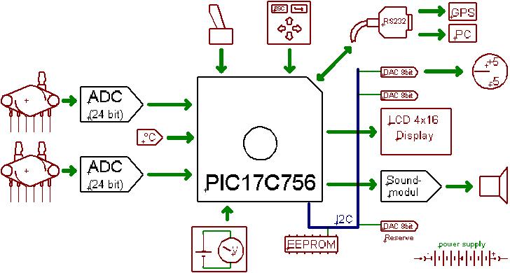
2.) Integrator
3.) Speed to fly
4.) Altimeter
5.) Speed indicator
6.) Final glide path calculator
7.) GPS interface
8.) Thermometer
9.) Battery voltage
The picture shows the components of the variometer. Two Motorola pressure sensors are used and their analog signal is converted to digital. The analog to digital converter is a 24 bit type from Analog Devices (AD771A). This high resolution is required because both signals, height and speed, have to be differentiated. For the speed sensor 24 bits are not really needed, but it makes sense to use the same ADC for both pressure sensors.
A 10 bit ADC is not enough for the differential pressure sensor! I had to learn this by trying to use the PIC-internal ADC for converting the differential pressure sensor signal. If you know about Nyquest then you will quickly figure out the reason for this. I didn't spend the effort to calculate the needed number of bits and just used the same high resolution ADC as I did for the altitude signal path.
The temperature measurement is done with a self calibrating technique las described in a Microchip application note. High resolution, robustness against capacitor aging and low cost are the advantages of this circuit. It consists of one thermistor, two resistors and one capacitor.
The electronic brain of the variometer is a PIC17C756. This microcontroller contains a 16 Kbytes EPROM program memory, which is more than enough for implementing the needed functionality.
There are several output devices. The LCD-display is a 4 x
16 character standard alphanumerical display. Because this low cost display
features user defined characters, it is possible to program a graphic needle bar.
The source code shows how to implement this. The result is a good to read
digital needle. Furthermore a mechanical instrument can be connected via the 8
bit digital to analog converter. The used MAX517
is connected
to a I2C
bus. This bus makes provides the control of several devices with only 2 wires.
The MR1-variometer contains four I2C ICs (1x EEPROM and
3x DACs). The second DAC is controlling the LCD-display contrast, which can be
set
comfortably via the MR1 firmware.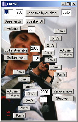
Of cause there is a acoustic output as well. I designed a special sound unit for this (you can think of it as a vario sound card ;-). This unit employs a PIC16F876 and a digital sinus generator IC (ML2036). Via RS232 it receives the climb value and whether the variometer or speed command mode is set. Furthermore this module understands instructions, for setting the volume and several initialization parameters. For development purpose a Windows test program was written. A screen shot can be seen on the right hand side. The program can trigger all commands of the sound unit. Every thing else can bee seen by going through the firmware. The Eagle file has all the hardware.
The sound unit works fine, but presents a costly solution. It may be better to connect the sinus generator chip directly to the PIC17C756. A interrupt controlled program then will control the sound.
The human interface is a keypad and a variometer/auto/speed-to-fly command switcher. It's connection is conventional. For details refer the schematic.
For sensor calibration coefficients and user data a EEPROM is available via I2C. All measurement results as well as the calculation of the sensor coefficients are summarized in an Excel file. If you want to start the development of your own E-Vario, remember that you will have to calibrate your hardware! Don't underestimate the effort it takes to build the calibration equipment!
A battery gauge is not really necessary but easy to implement. Only two resistors and some lines of firmware are needed. It's a little effort and nice to know your battery voltage.
Because the detailed schematics are to big
to be shown on a
web page, you should download the light version of Eagle
from the
Cadsoft homepage. With this program you can open the schematics and PCBs
to viewing
and modify it for your own, non commercial needs. 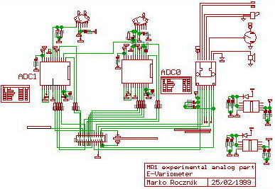
Eagle is a very powerful and easy to use PCB program. After two hours of "learning by clicking" you will be able to enter schematics, define new devices and design PCBs.
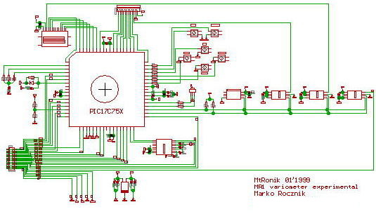
The test setup was split into two boards. One contains the analog and the other one the digital part of the circuit. Both PCBs are connected via a 24 pin connector.
The digital PCB features a pin grid. Test circuits can
be soldered there. This pin grid as well as the footprint for the LCD display
has been placed outside of the "light" area restrictions of Eagle light. This is
possible, by using a little trick: Design the footprint of the device this way,
that after you placed it into the PCB design, the origin will stay inside the
valid area, but the structures will be outside there you want them.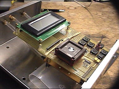
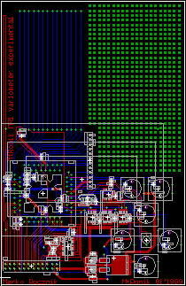
The layout is shown on the left hand side. A aluminum box shields the variometer from the outside and the environment from the inside.
Equipped with pressure ports and a Western connector for the electrical connection the hardware is ready for test flights.
Once the hardware was there the real work started: developing the MR1 firmware. My "C" source code is available here. It features all low level hardware control, measurement functions and test programs. It enables you to test the variometer in the air.
In the first place I planed to drive the develop of this variometer to the state which would enable me to do a small volume production. Unfortunately I became very busy toward the end of University. Later during my PhD the situation didn't changed and so I did decide, to publish my development. You can find all circuits, firmware, programs and documents which I developed for the variometer on this website. Developing the variometer was a lot fun to me and I hope to motivate someone out there to start your own project. But I want to warn people who think taht they could save money by building a e-variometer. If you belong to these people I can only say "don't try!". To develop a reliable, robust and really good working variometer is a lot of effort, way more work and then simply to buy one for money.
If you want to build the MR1 electronic variometer you may ask me for advice. Please don't expect more than a hint, I will not write you new code or even design new circuits! You can use all the files for your own needs as long as it's non commercial. If you want to publishing it on a other place, then you have to refer the source. It is not allowed to use this development, or part of it, for commercial purposes!
Have fun!
Impressum, Disclaimer & Datenschutz
![]()