German
3D Laser Scanner
While most
aircraft designer have the problem to get a shape out of their computer
into reality, I have the exact opposite problem. I got an old fiber
glass fuselage along with blue prints from the 80s and need to get this
into my 3D-CAD system.
The following will show the way I digitized the J5 fuselage. I will start with the motivation, why an aircraft designer needs a 3D aircraft laser scanner:
Thinking (while holding the engine) 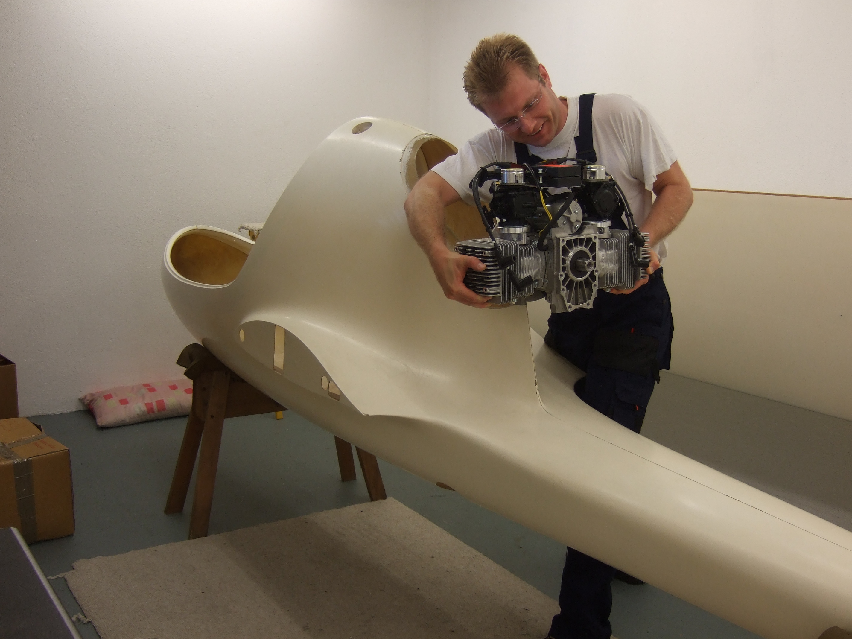
The old KFM engine originally used for the J5 is not available anymore. Also it doesn't present the state of the art. A new engine does not only require a redesign of the engine mount, but of the entire aircraft (leading forces from the engine to the wing, resonant design, exhaust system, thermo system, safety cockpit, ...ect.). In the beginning I thought that this can be done old school using mockups. But once I held the heavy metal piece (called engine) for a while with my hands I realized that I can't think strait while my muscles start to hurt. It was pretty clear: 3D-CAD is the way to go in the 21st century.
I already 3D designed an engine test setup
for the J5 and was amazed how well the result matched the 3D modeled
idea. Memories of building glider trailers from napkin sketches looked
very different! Also very attractive is that 3D modeled parts can
be simulated. While these simulations can't replace a stress test, they
show very precise weaknesses in a design.
Even after this means a whole lot of
effort, it will pay back for the experimental builder and
designer! Especially the chance to simulate parts and assemblies,
provide a deep understanding of the design. It forces the designer to
think about the loads and shows the stress in the parts. Once the 3D
data is there, future builder have the chance to get new CNC molds
build. This reincarnates "non home build able" designs. Finally besides
saving aviation history, 3D models are a great way of documentation.
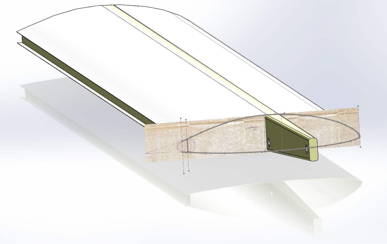 plan inaccuracy (spar doesn't fit the wing)
Of cause I started digitizing the original blue prints. Naively I expected that the plans would fit the parts. Disappointed I had to realize that this was not the case for the 80s blue prints. In the example above, the spars dimensions are measured from the part while the airfoil dimensions come from the plan. As you can see the spar sticks out of the wing. The inaccuracy in this area is about 1 cm.
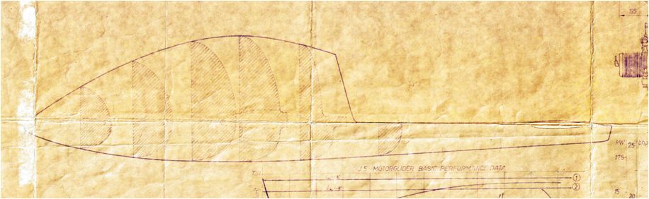
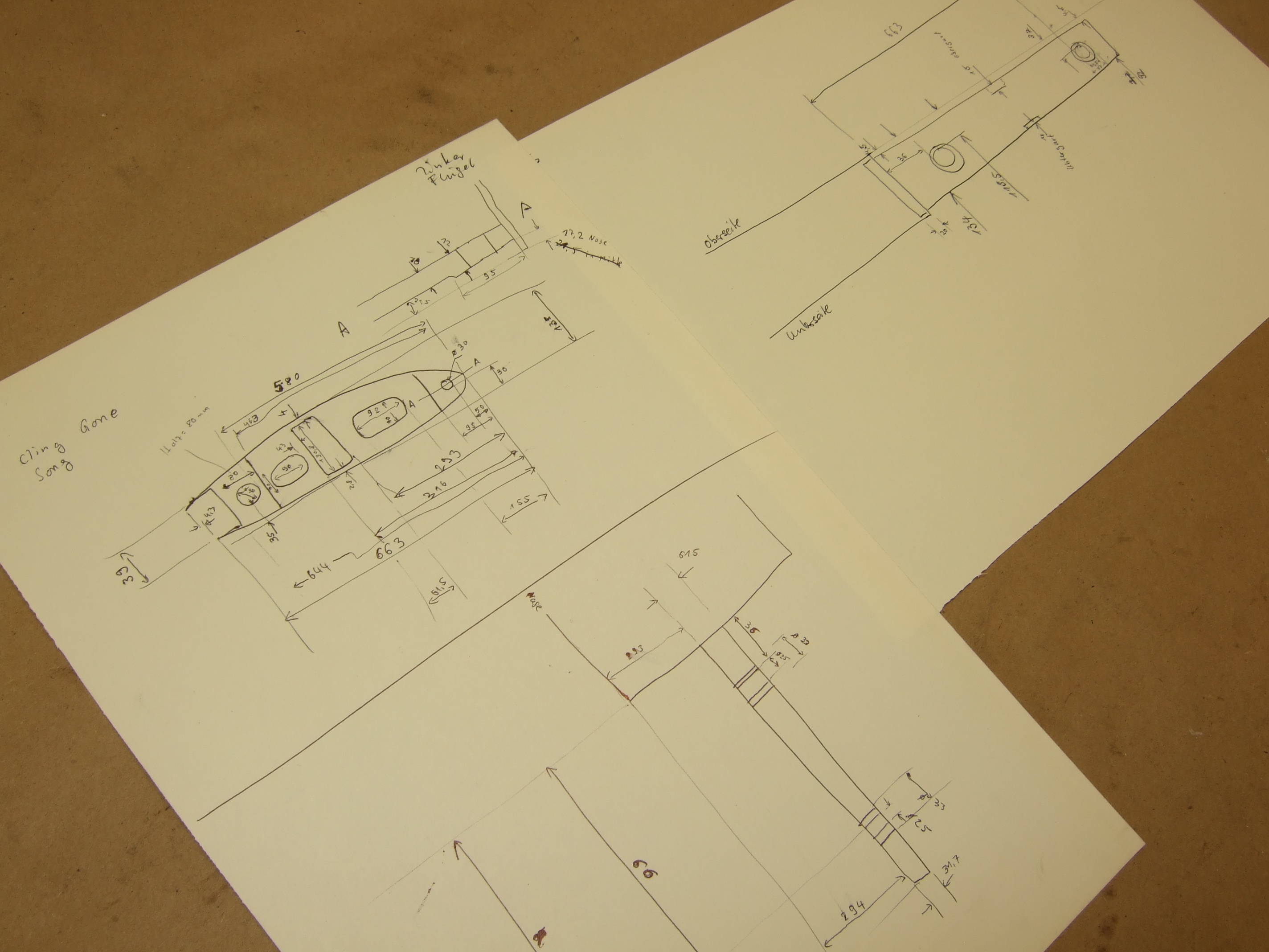
Looking at the fuselage blue prints, one quickly
realizes that you can't do a 3D model with sufficient accuracy from
this source.
3D model from plan cross sections 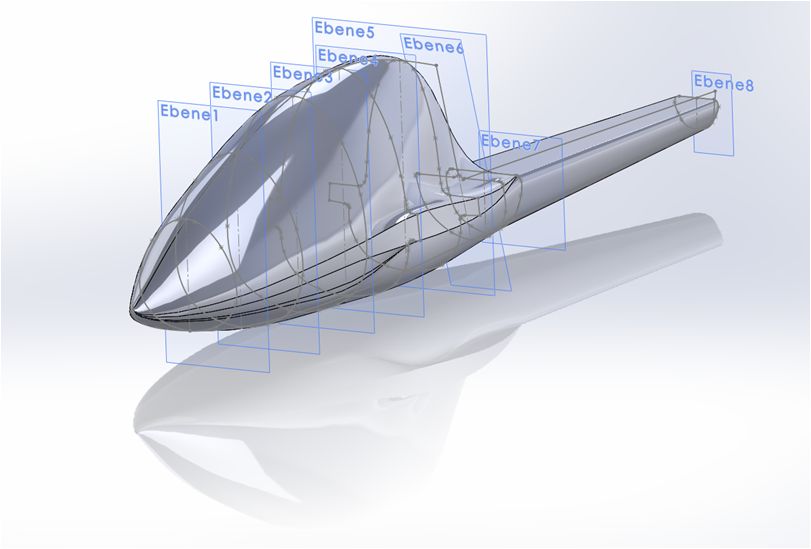
As a trial I entered the plan cross sections into the 3D CAD tool. Quickly I realized that I need exact measurements from the real parts if I wanted to use them.
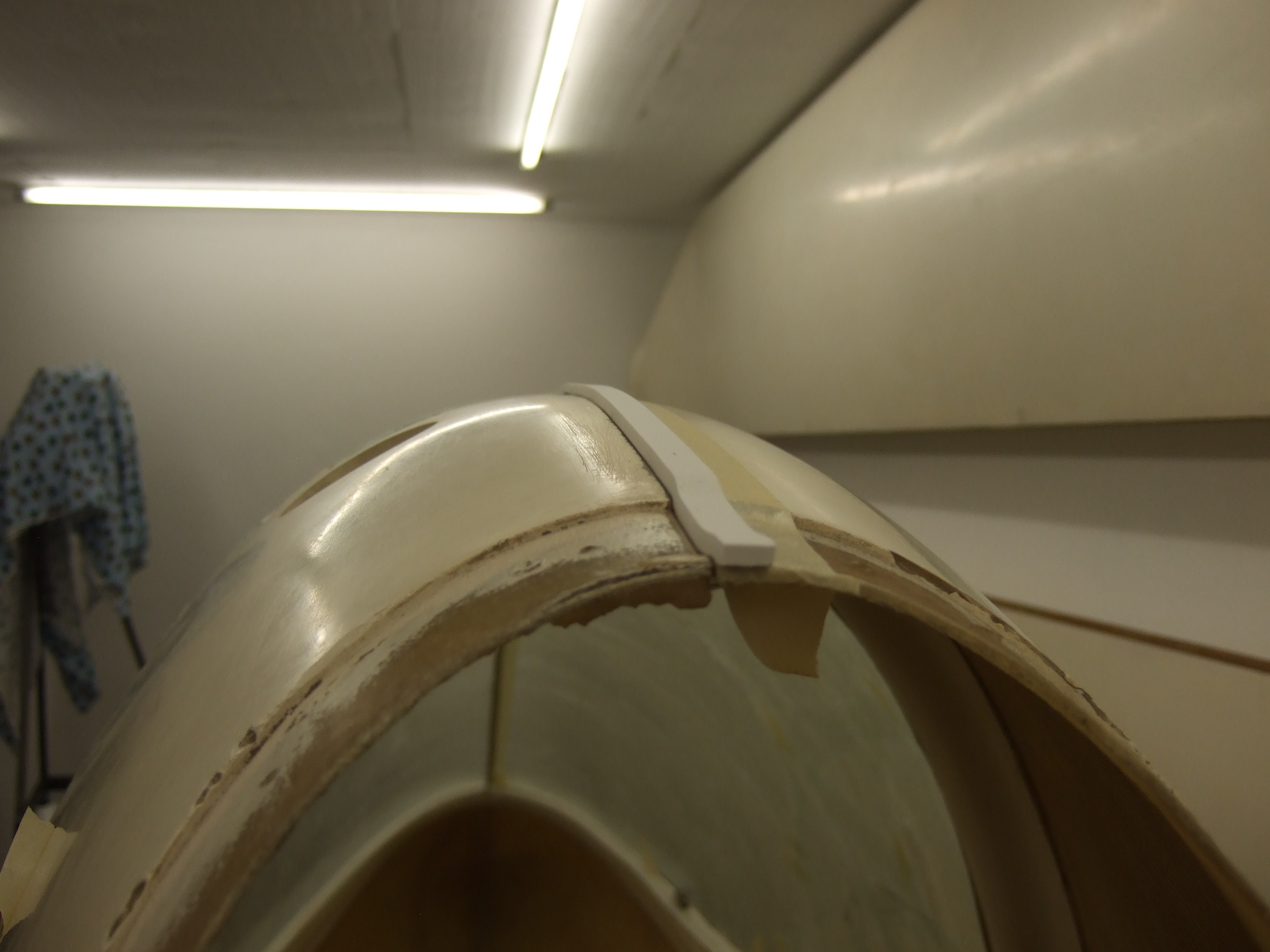
The 3D model requires accurate cross sections of the fuselage. To get these, one needs to measure the Y- distance relative to a reference. Doing this for all Z- values generates the cross section. Several of these cross sections are needed to generate a complete model of the fuselage.
The
measurement of the wing root showed how much effort and chances for
error are in the manual measurement method. Especially a mechanical
reference is a challenge. In contrast to the low complex wing root, the
spherical surface of the fuselage would be very difficult to measure.
In order to get any useful data, a complex mechanical measuring device
would have to be build. So the pure manual measurement didn't make any
sense and was dropped.
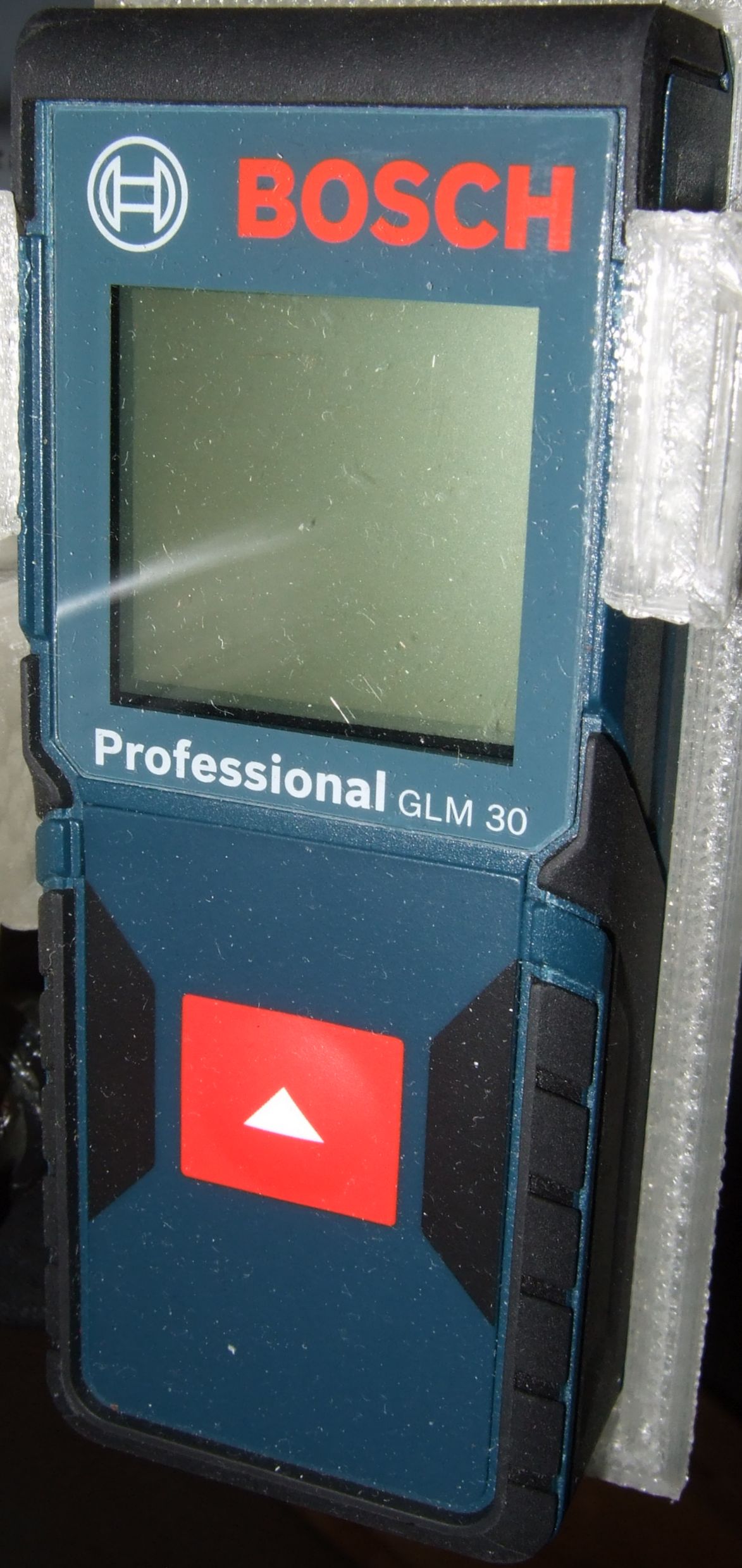
But there is a great alternative: Laser distance measurer!
These
devices send a laser beam, which partially reflects at the object. From
the run time of the returning laser light a detector figures out the
object distance. Common online stored sell these devices at reasonable
prices.
So I came up with the following idea:
I take one of these laser distance measurer and let it drive up and down a rod. The drive is done by a M6 threaded bar. A nut turning on such a bar is moving 1 mm per revolution. The nuts are packed into adapters to fit into a geared motor. Such a geared motor can be bought cheap e.g. at Pollin (I paid 15€ in 2015). This geared motor does 1 turn every 2 seconds. This is slow enough to count the revolutions.
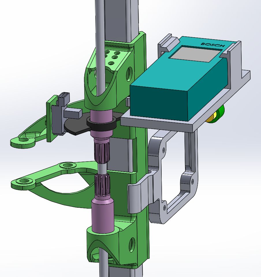
For counting the turns I found an very cheap light barrier which comes completely assembled and has an open drain output. An half disc interrupts the light beam every 180°. The light barrier sits together with the half disc at the spindle drive.
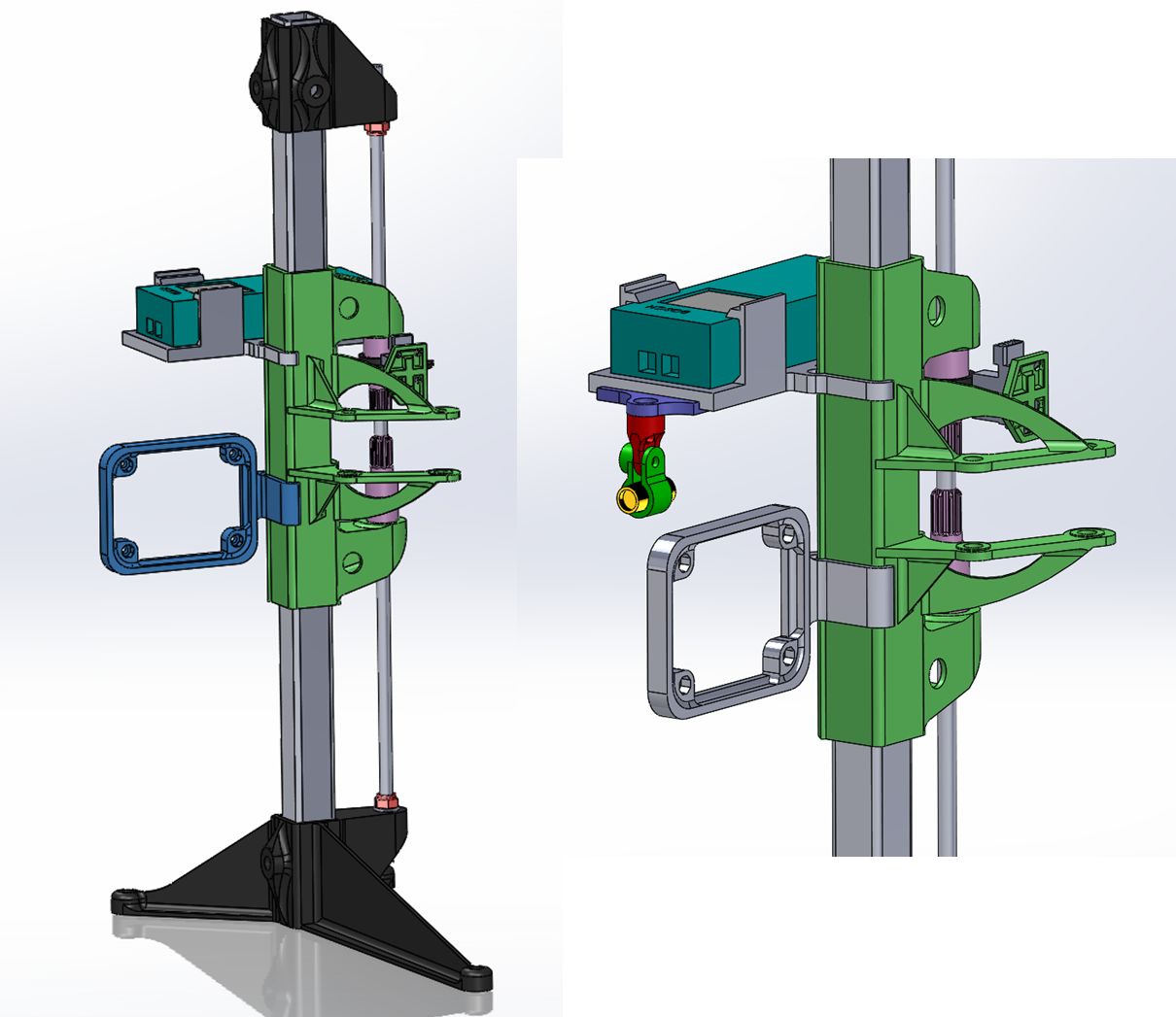
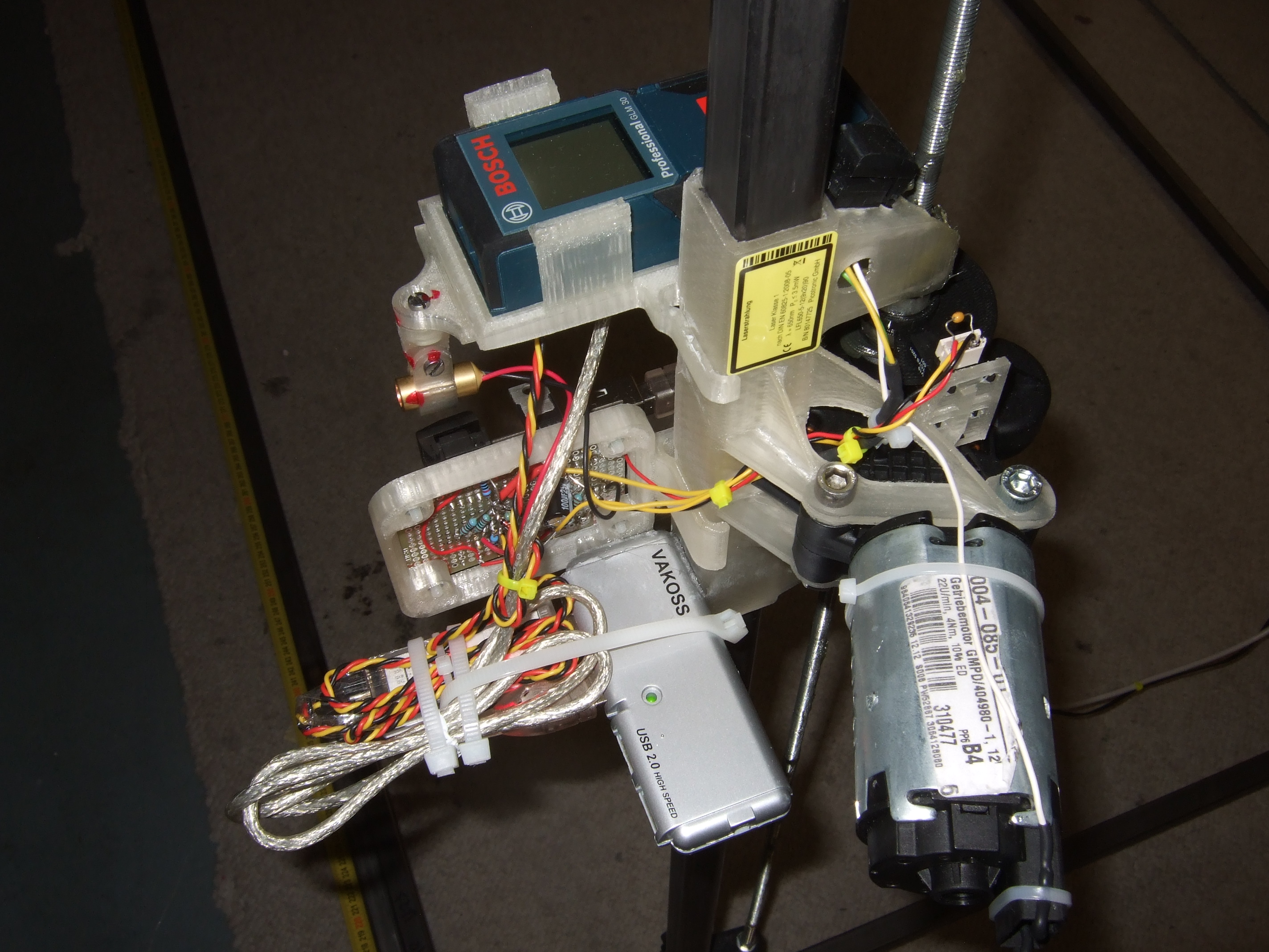
Finally we need an holder for the geared motor, the electronics as well as a adjustable holder for a line laser. The later one makes your life way easier aligning the laser scanner as we will see below.
The result is a profile scanner. Further down I will show how to get from the idea to the working thing with just a few clicks. Above you can see the 3D modeled idea along with the realization.
Mechanically we are done. Now we got to bring together the whole thing electronically.
What we got is the laser distance measurer with a USB port and a computer whose job it is to collect the measurements. For control we have to make the motor turn right and left and to read back the light barrier.
So we connect a ordinary USB hub to the computer and plug in the laser distance measurer.
There are very affordable USB modules available (e.g. DLP-2232H), which enable even the hobbyists to in- and output electrical signals. While the motor gets soldered via a bridge driver (TLE5206) to such a module, the line laser can be connected directly. This electrical system is fairly simple.
All electronics are soldered to a breadboard. In the picture above you can see the USB module along with the bridge driver for the motor. Two switches can overwrite the electronics to enforce manual control.
This picture shows the USB hub. Since these are darn cheap these days I simply glued it using superglue. What else you can see on the picture are two end position switches. If for any reason the motor wants to drive beyond the ends, the power is cut. The rest of the electronic is limited to a couple of resistors and capacitors.
The electronic was designed and build in our high tech lab shown above. While my wife took David to Kindergarten, I took the chance to join Sara's craft session (supervised by Tim ;-)
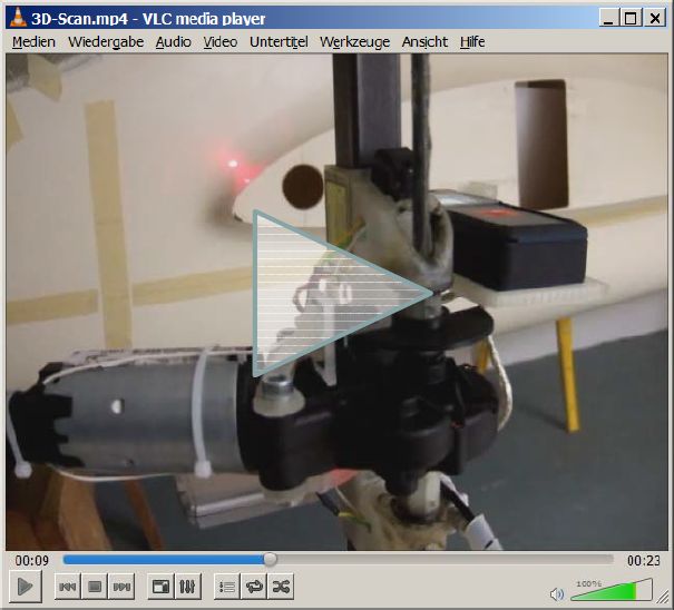
The Video shows the whole thing in action:
The geared motor spins the spindle drive and moves the scan head. The motor stops every 2nd revolution for the laser to take a measurement. The process looks slow and also is supposed to be slow: The simple electronic combined with a very simply control program forbids a fast movement of the scan head.
The missing piece now is the control program. I wrote the functions in C and compiled it using National Instruments CVI (Very good compiler - never had an issue with it!). The graphical user interface is shown above. In order to move the scan head manually you enter the wanted mm up or down at the field "manual control". This way you move the scanner into the starting position (z = 0). If you want to scan, then all you got to do is to say how many mm up and down you want at which resolution, hit the "Scan" button and you are all set.
While the Z- and Y- values are gathered automatically, the X- coordinate (station) is entered manually into the software. By saying "manually" I mean, that you really read a tape measure and enter the mm value. So the 3D scanner is half automated which is a compromise between comfort and building effort.
Data is saved into text files, which can later be imported into the 3D CAD tool as a XYZ curve.
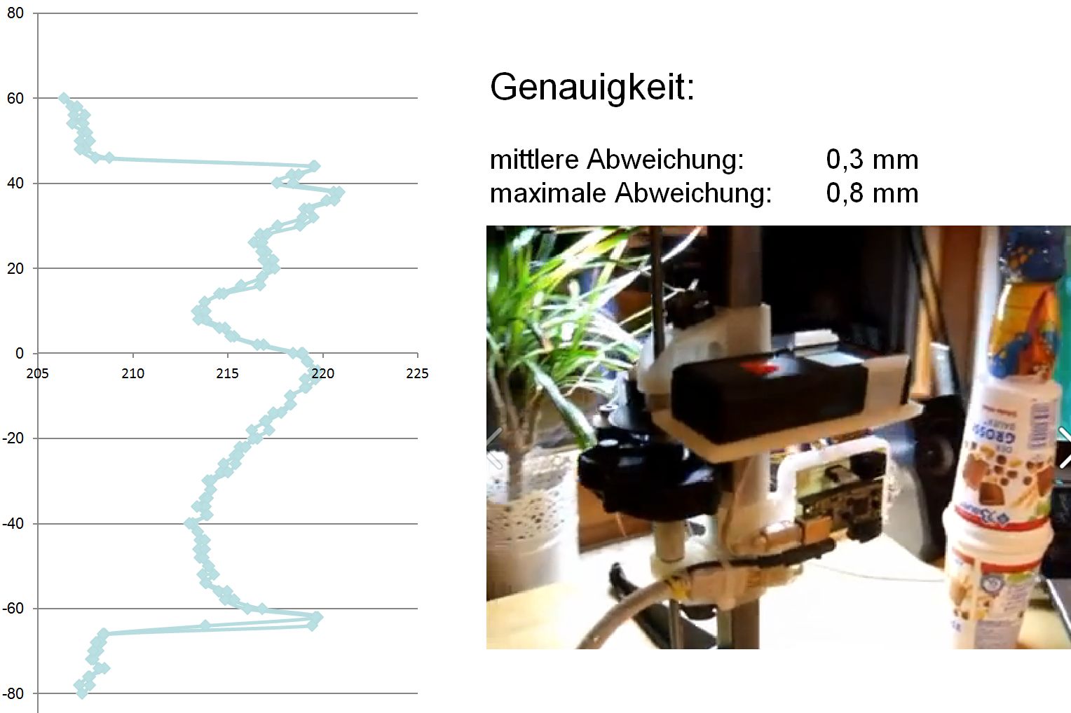
One big questions of cause is: How accurate is
this? Laser distance measurer promises an accuracy of +/- 2mm. But in
reality they are way better! In the example shown above I'm scanning my
son's yogurt cup. Because of its shape it can't be used for resin
mixing, but it's good enough as a scan object. I imported the
values into Excel and calculated the maximum and average deviation. The
result was surprisingly good:
0,3 mm average,
0,8 mm maximum
deviation!
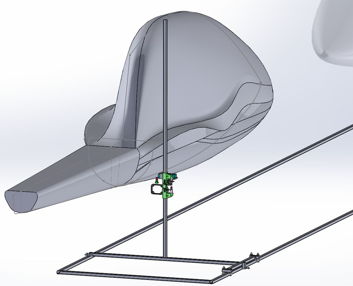
Now that we got the scan head up and running we need a setup which allows to move it in X- direction. The modeled idea consists of 20x20x2 squared steel tubes. These are affordable to get at the local steel dealer (don't go to the home improvement stores - they are way too expensive!). I placed two 6 m long pieces at the floor which functioned as rails. Diverting from the picture above I figured that you don't need the cross bars since the own weight of the rails is already good enough to keep them in place.
I welded the little cart out of 3 tubes. It must
be noted that it is practically impossible to get the upright pole
absolute exactly vertical. This is especially due to the thermal
welding stress. In the following we will see, that this is not a
problem since reference marks on the fuselage will correct this.
Before building, the idea was 3D modeled.
One detail of the sled are the rollers. In times of inline skates you can buy these as 16 piece bundles for cheap money. In the beginning I wanted to use skids, but applying roller bearing made the thing much easier and simpler.
During a scan a simple screw is holding the sled in place.
The Video shows how easy the sled is moving on the tracks: > Video - Click < !
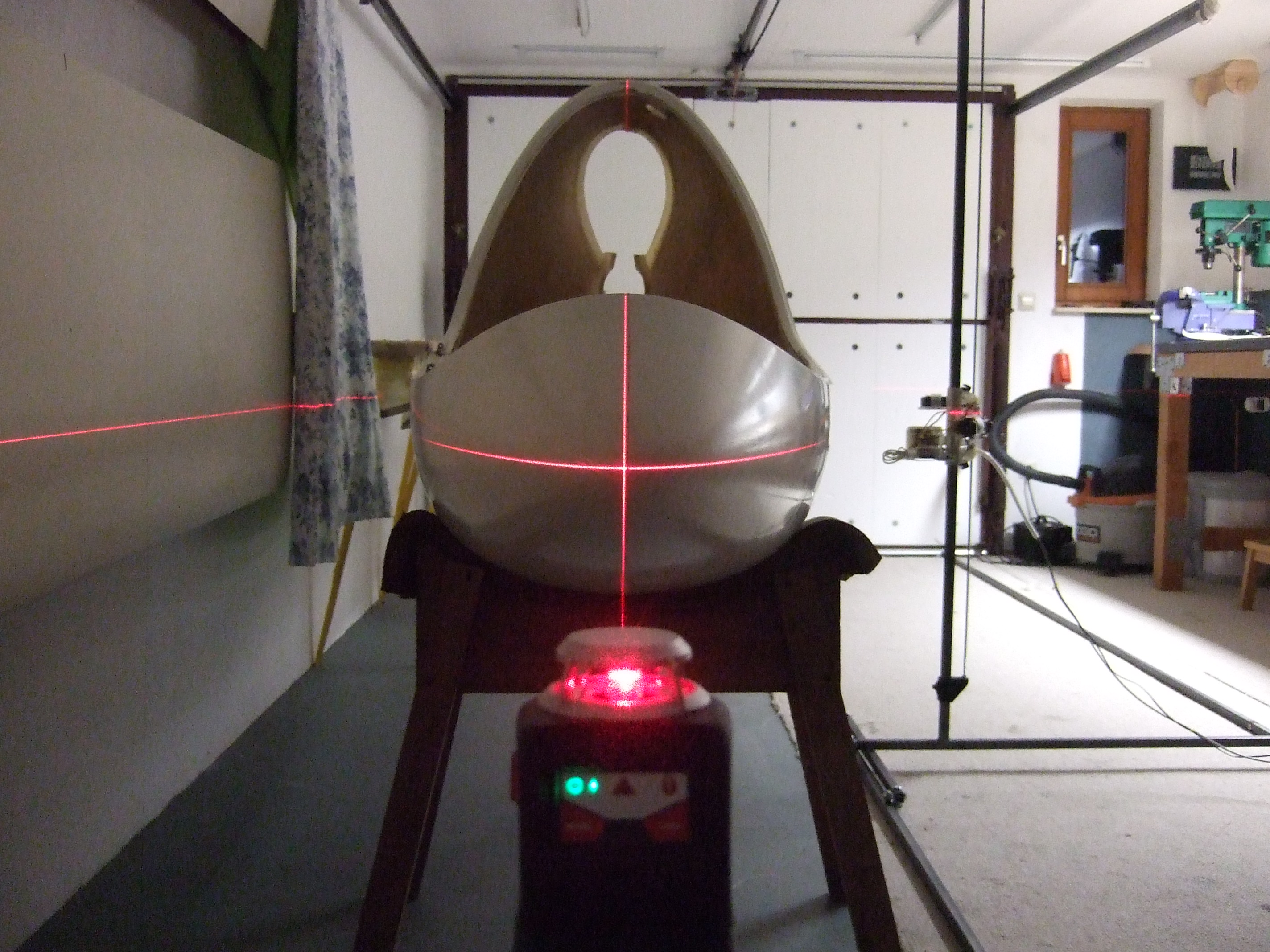
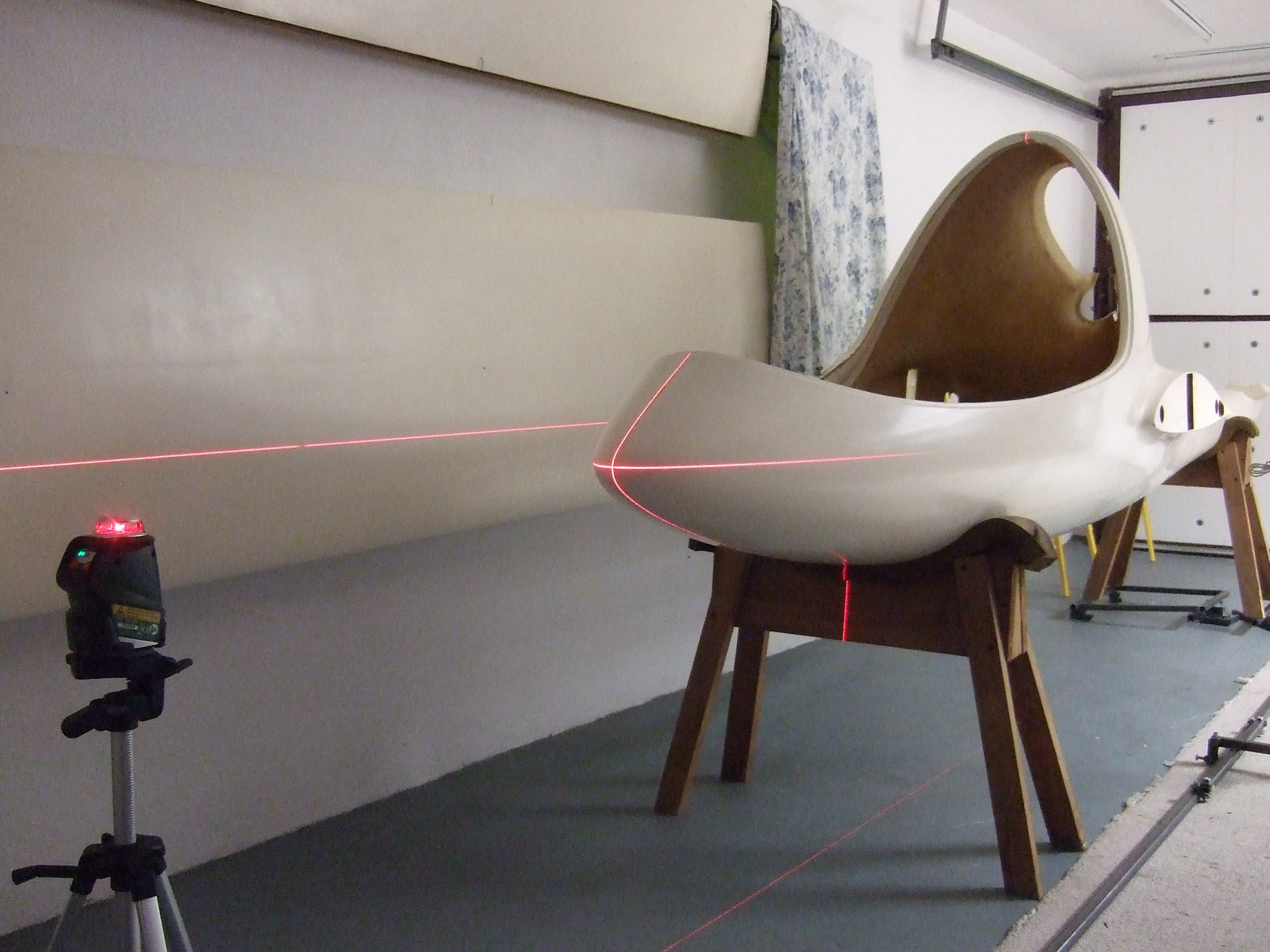
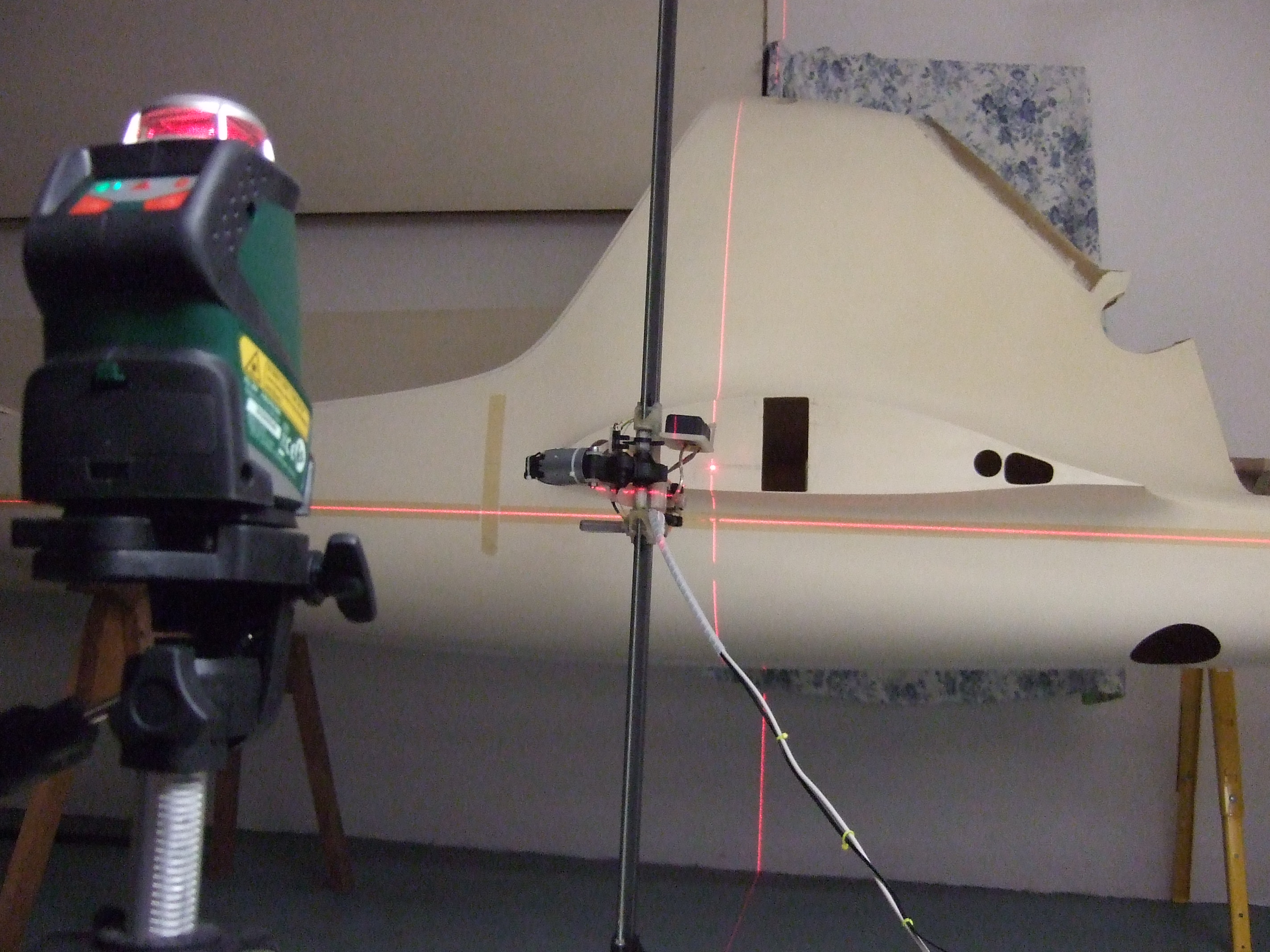
Design and building of the scanner went pretty fast. What took quite some time was the alignment of the scan object. Essential is a cross line laser level (e.g. from BOSCH).
With the fuselage aligned you can now nicely see the angle of incidence.
Aligning a several meter large object with mm
accuracy is a mission impossible. I spend a whole evening moving the
fuselage, until I finally gave up and went frustrated to bed.
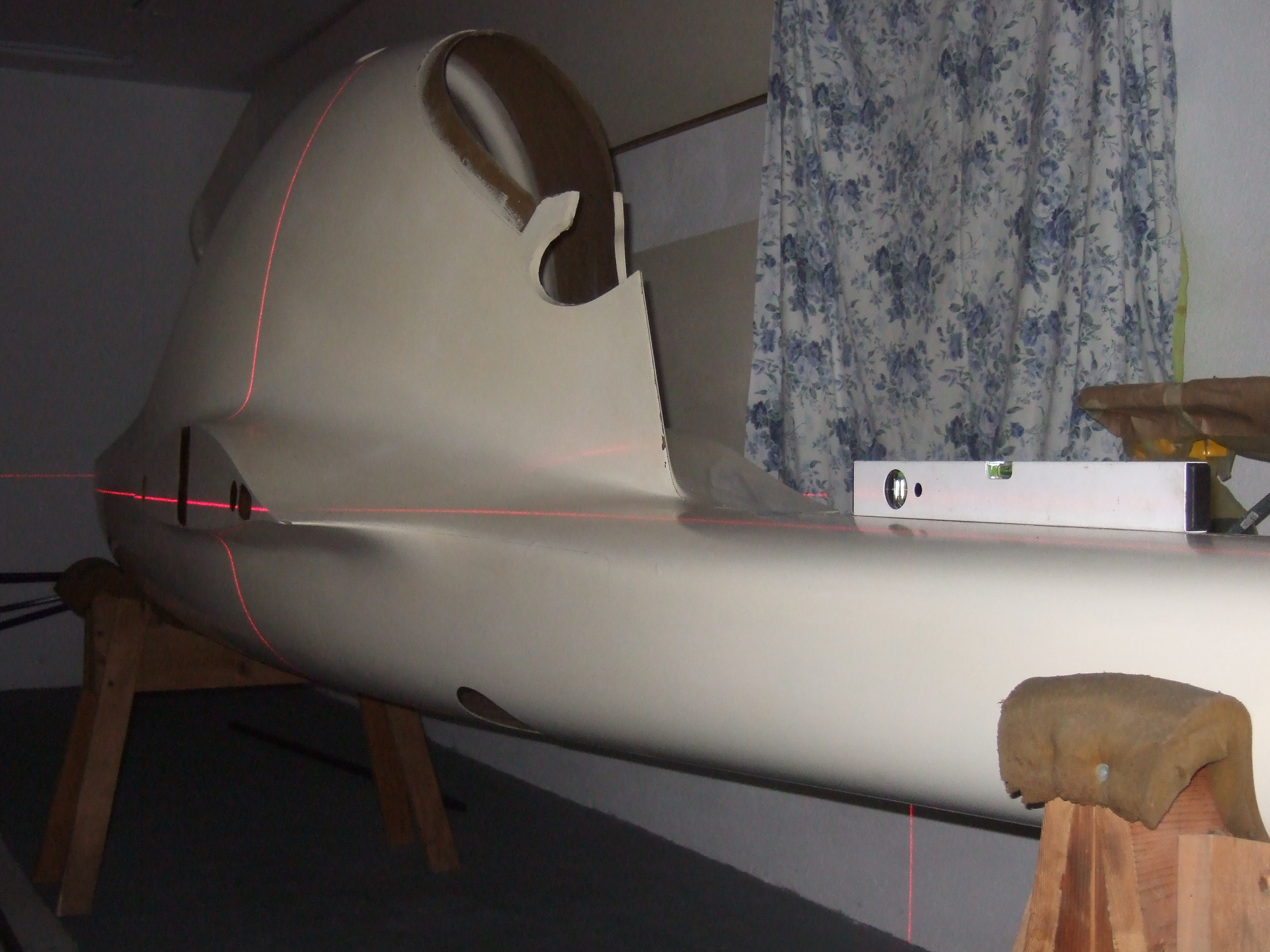
The next morning it came to my mind, that the exact alignment wasn't necessary. Applying a z = 0 mark at the fuselage would do the job. This can easily be made with a line laser level, masking tape and a pen.
Every scan process starts with the calibration at the z = 0 reference line.
No there are two more sources of error:
1.) the vertical sled pole might not be vertical
2.) the fuselage is not vertical in the fuselage stand.
But both can be corrected numerically by using center marks. These marks will be visible in the scans and the curve can be numerically turned into the correct position. For the markings I used the cheapest roll of 5 mm window sealing tape I could find on Ebay.
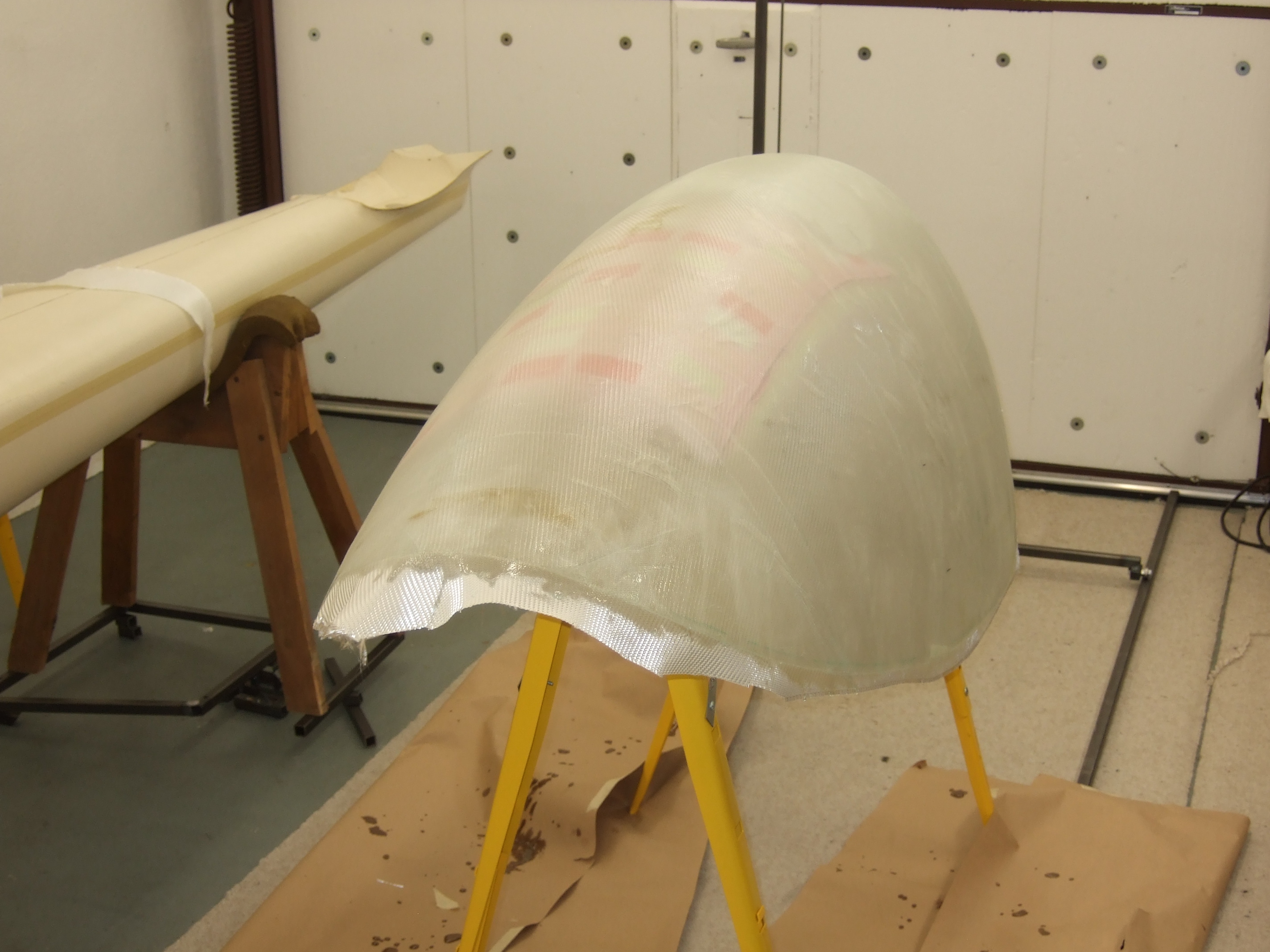
Before
scanning I spend one more night laying up a dummy canopy. I wasn't sure
how well the laser beam would handle the transparent Plexiglas. While
the resin was curing I thought, that simply painting the canopy with
water paint would also have done the job. Well - building an aircraft
is a learning process.
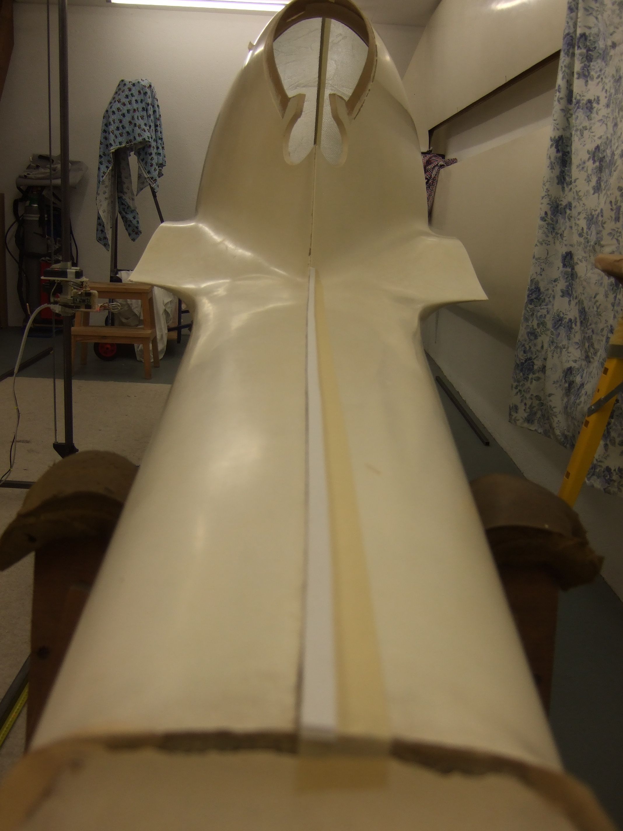
After the alignment and the dummy canopy the scans could be started. I used the wing nose as the x = 0 reference. The pictures show the scan process toward the cockpit.
Now I scanned the cross sections station by station. The data then was imported into a 3D CAD program.
Here you can see the visualized raw data. Even after there needs to be quite some post processing done, you can see the general fuselage shape along with the reference markings. To finalize the data, start and end points need to be assigned, the z offset corrected and the cross section angle corrected (using the marks).
Afterwards the scans are ready to use as the reference for building the 3D model.
Let's stop here with the scanning and talk about the fabrication of the scanner parts:
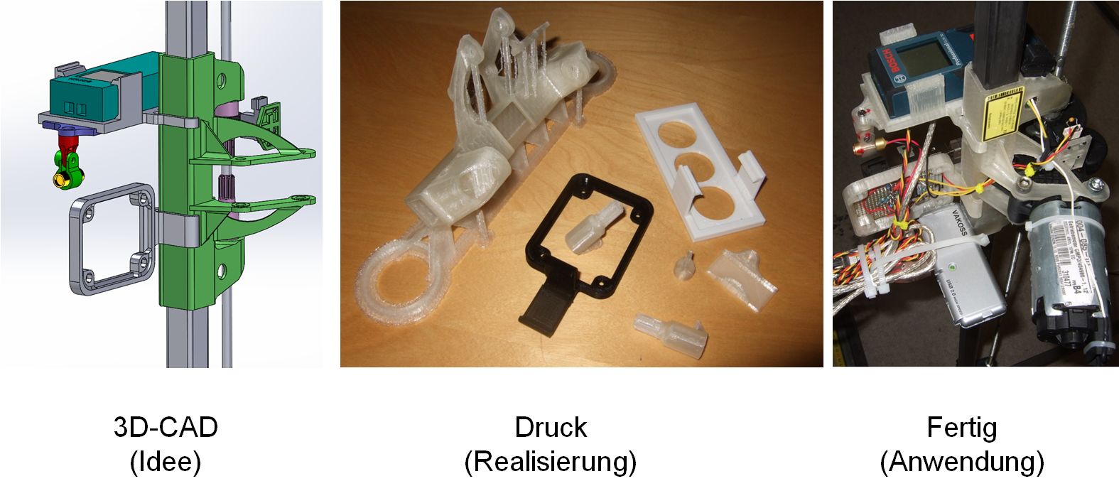
The construction of the 3D scanner is making extensive use of 3D printing techniques. The advantage is, that you can design any shape you want to and finally simply print it. The picture shows the path from the 3D modeled idea, via the printed parts to the functional assembled object.
Listed below are the major parts with their print times, to give you a feeling for how long it takes to print:
- laser joint 12 min
- spindle nut housing 15 min
- line laser holder 25 min
- distance measurer holder 40 min
- electronic holder 45 min
- main frame 6 h
I presented my aircraft 3D laser scanner at the OUV winter convention in the iMAX theatre of the technical museum Speyer (Germany). Since it ignited lots of interest I offer some files for download.
Attention: Whoever is playing with these things needs to be an expert an know what he/she is doing! I do not take any responsibility for things people do with these files, my design or idea in general!
C core source files for control program (11 kByte)
Video Scanner in action (2,7 MByte)
All data can be used for personal purposes, for hobbyists and especially for experimental aircraft builder. Commercial use of my intellectual property requires my permission.
Impressum, Disclaimer & Datenschutz
 3D Laser Scanner idea
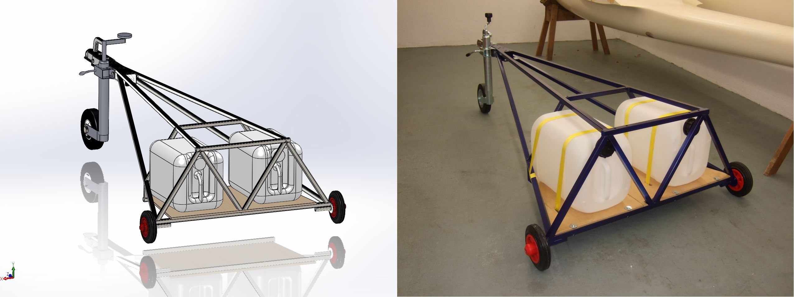 3D to Real
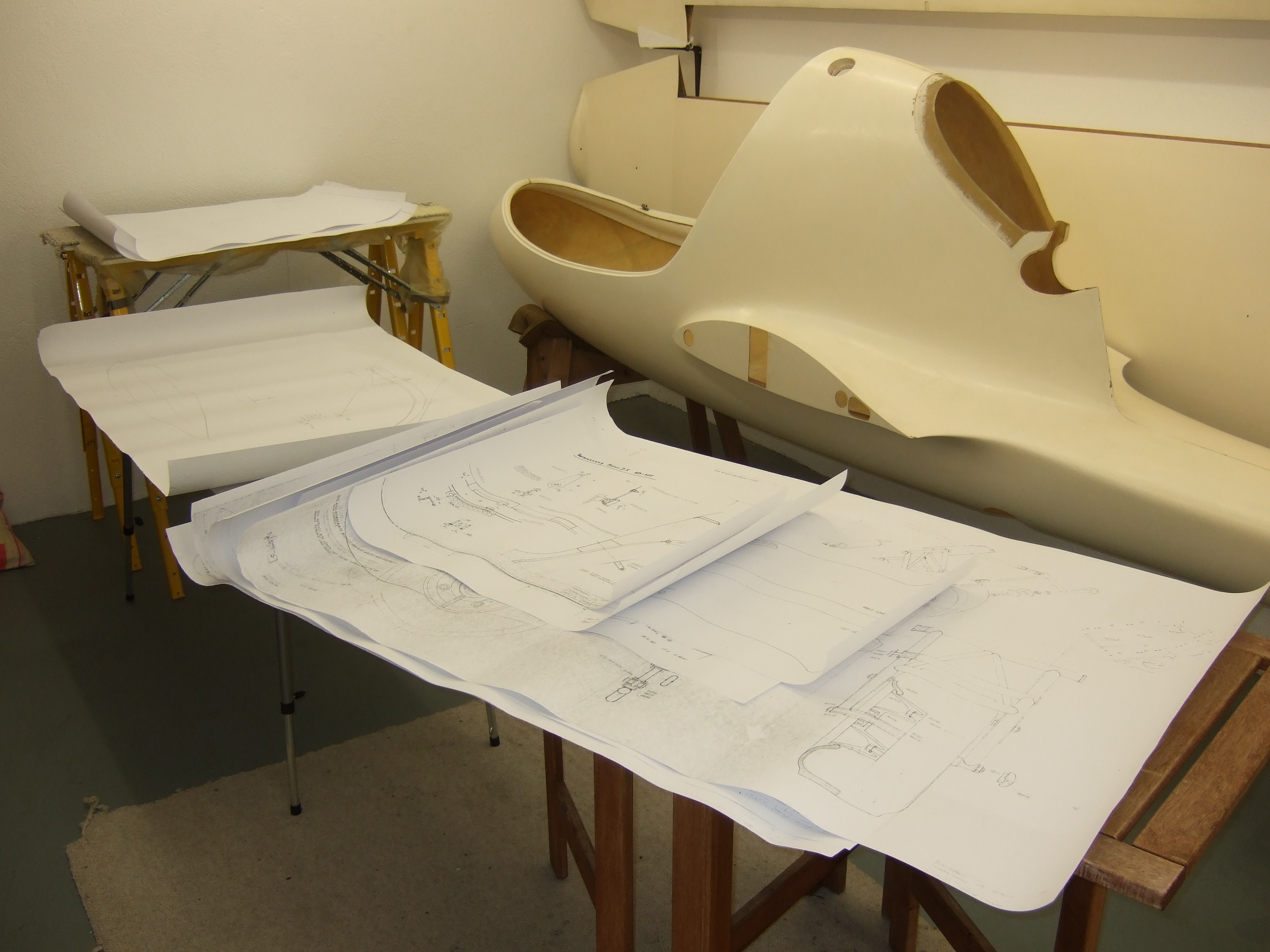
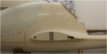 detailed mid fuselage
 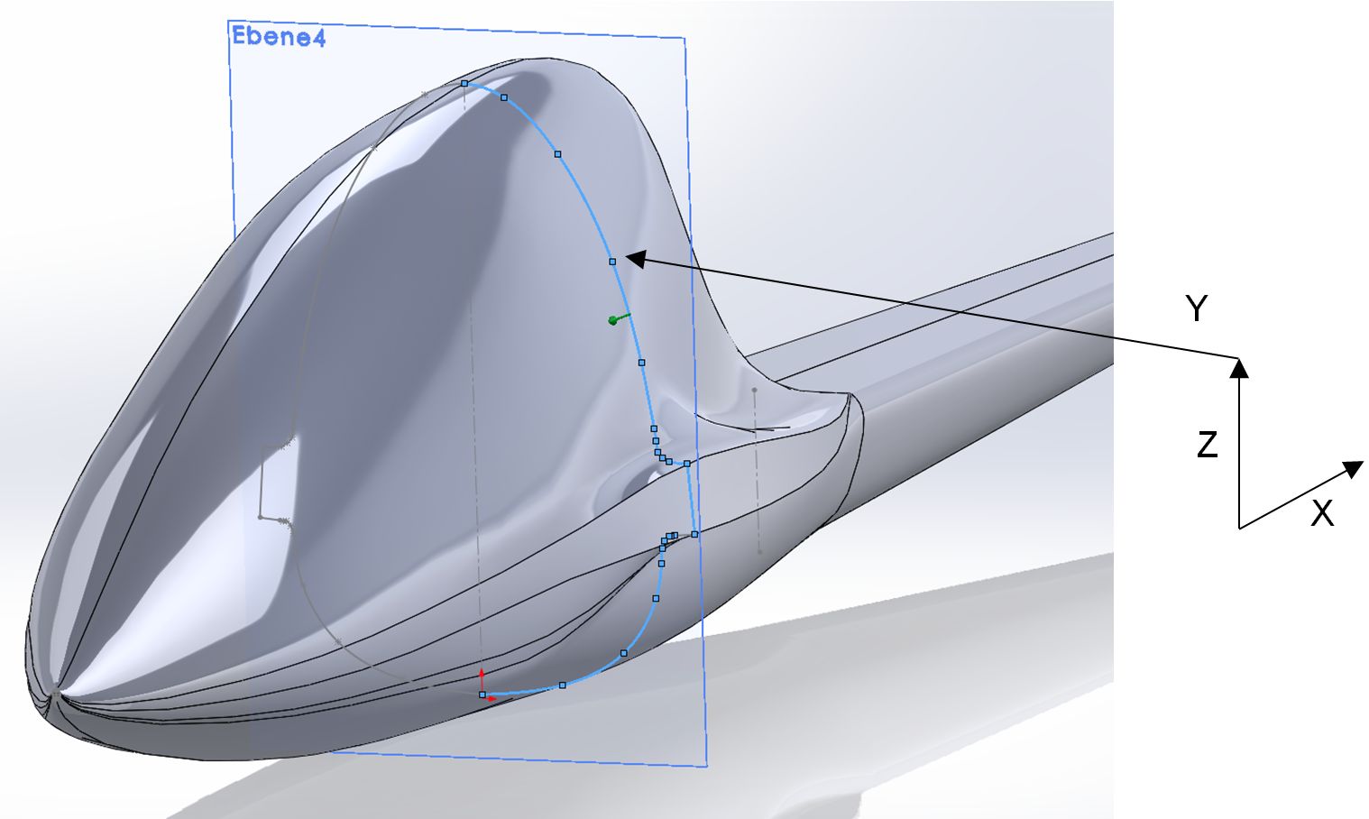 measurement task
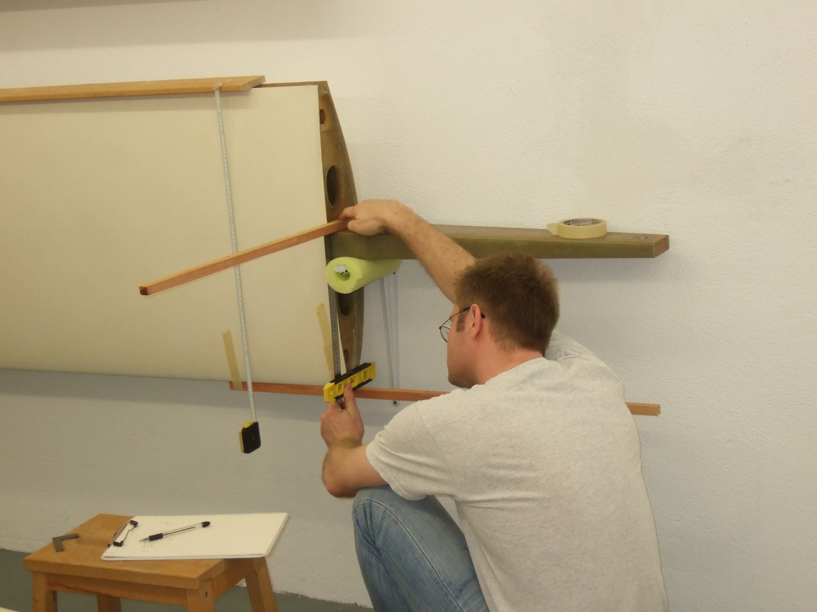
 laser distance measurer
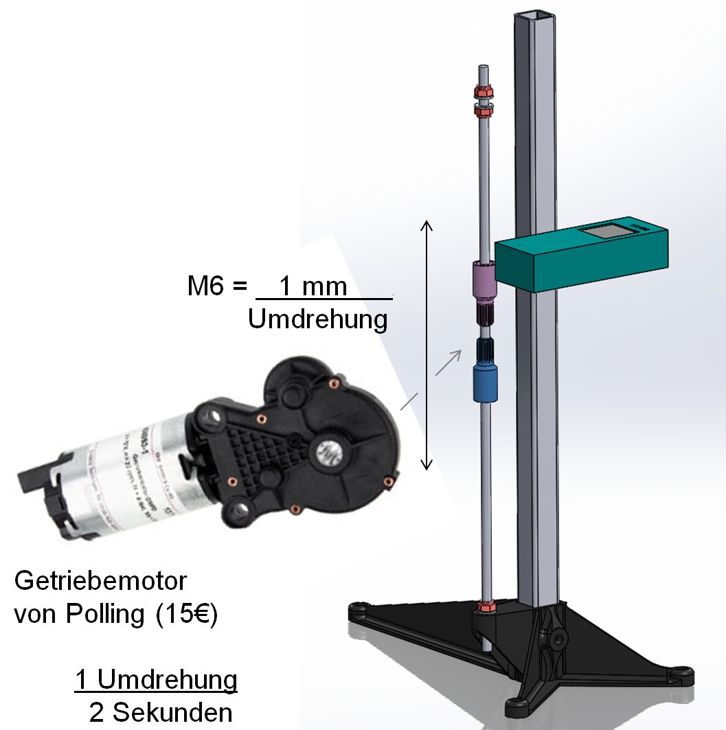
 light barrier
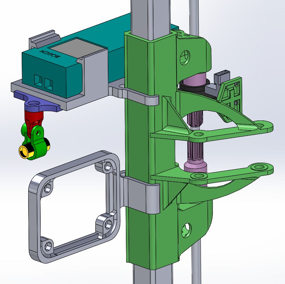
 measurement head
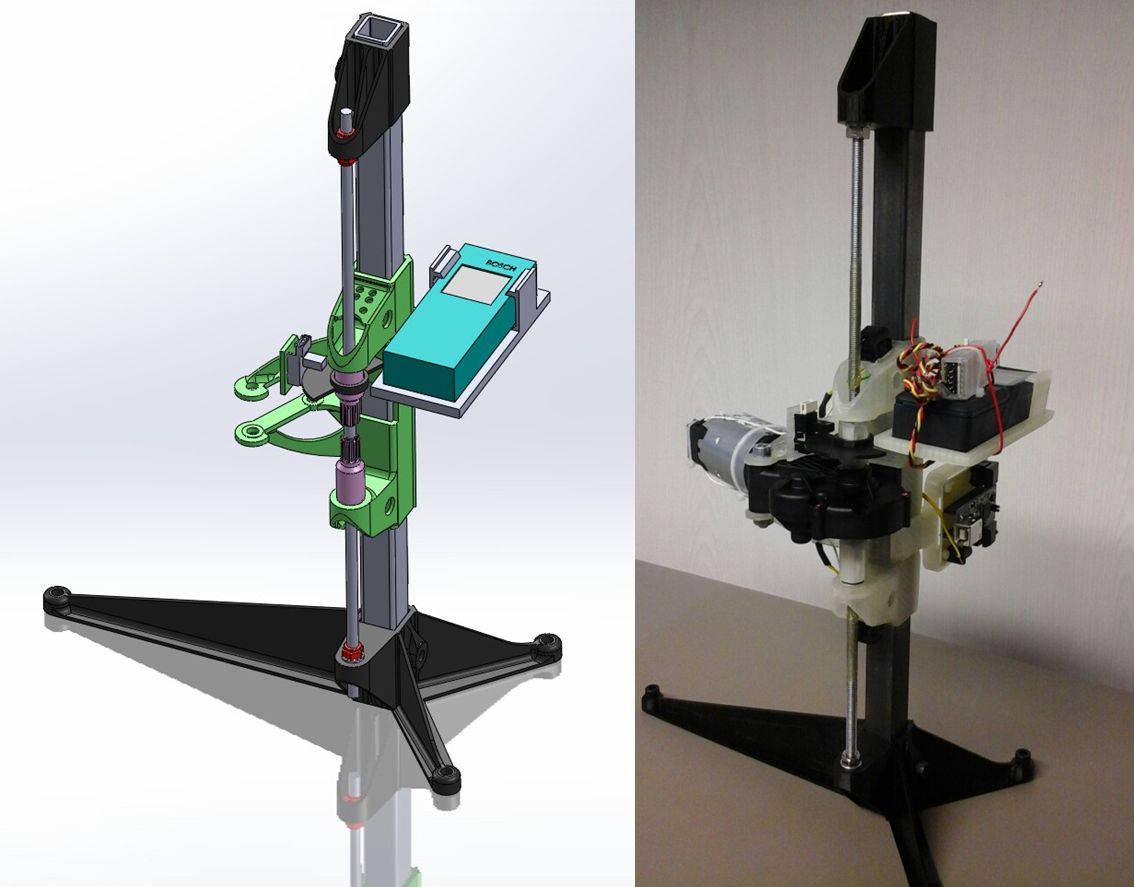 >> Reality
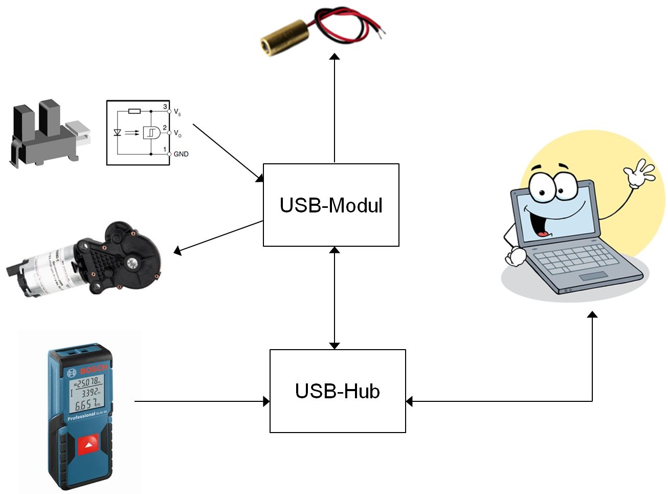 electric control
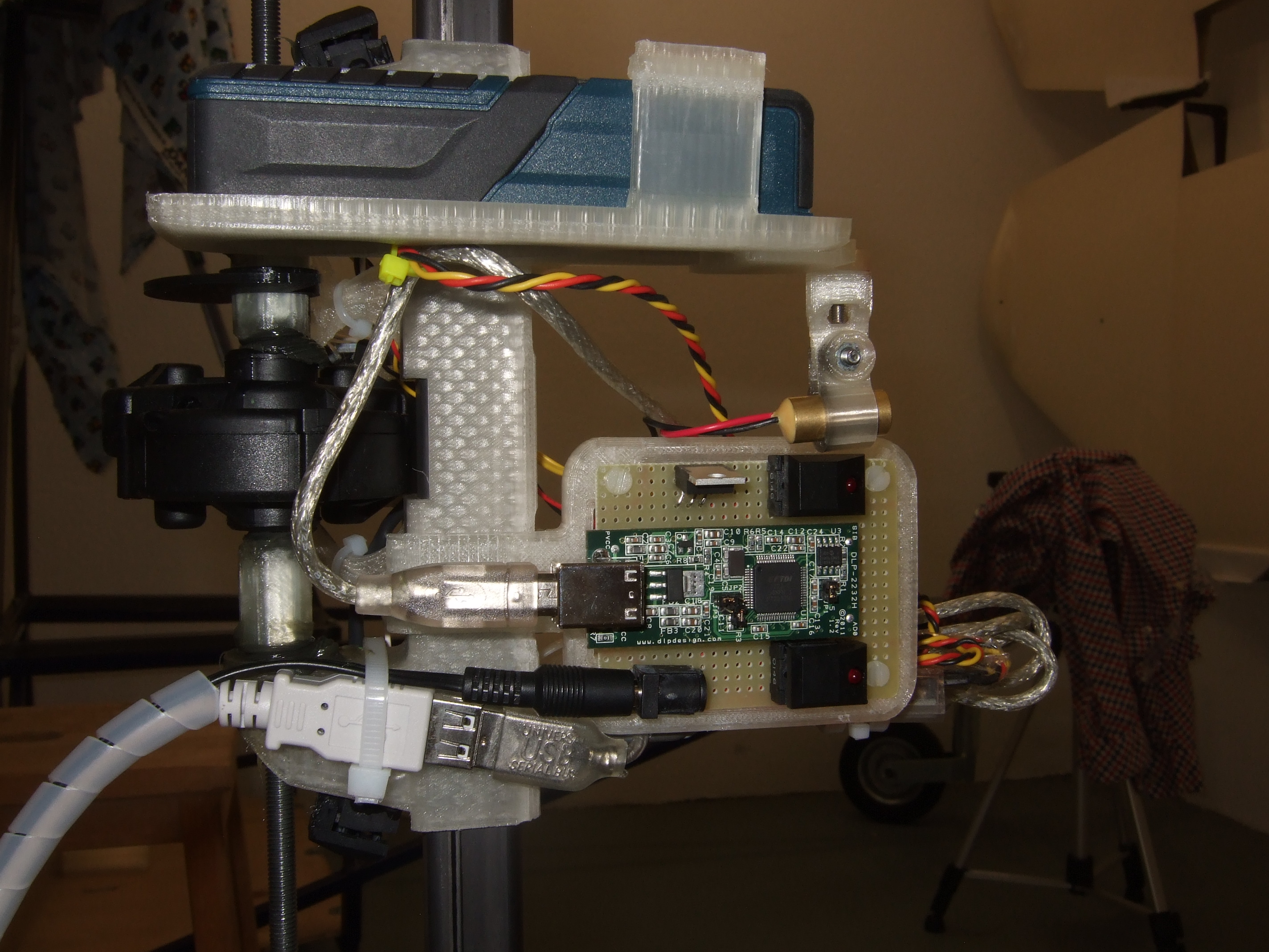
 USB Hub
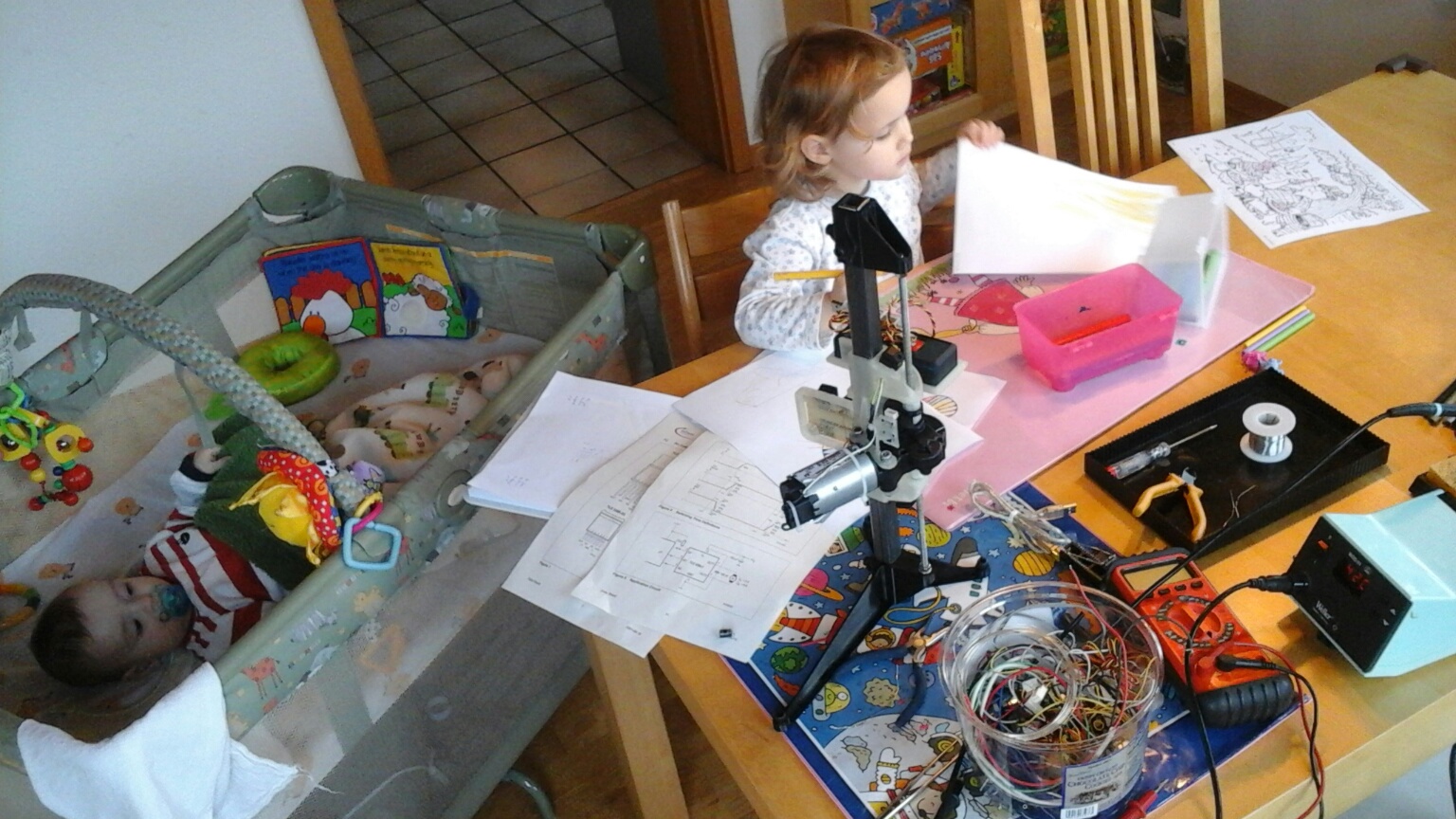
 Video >
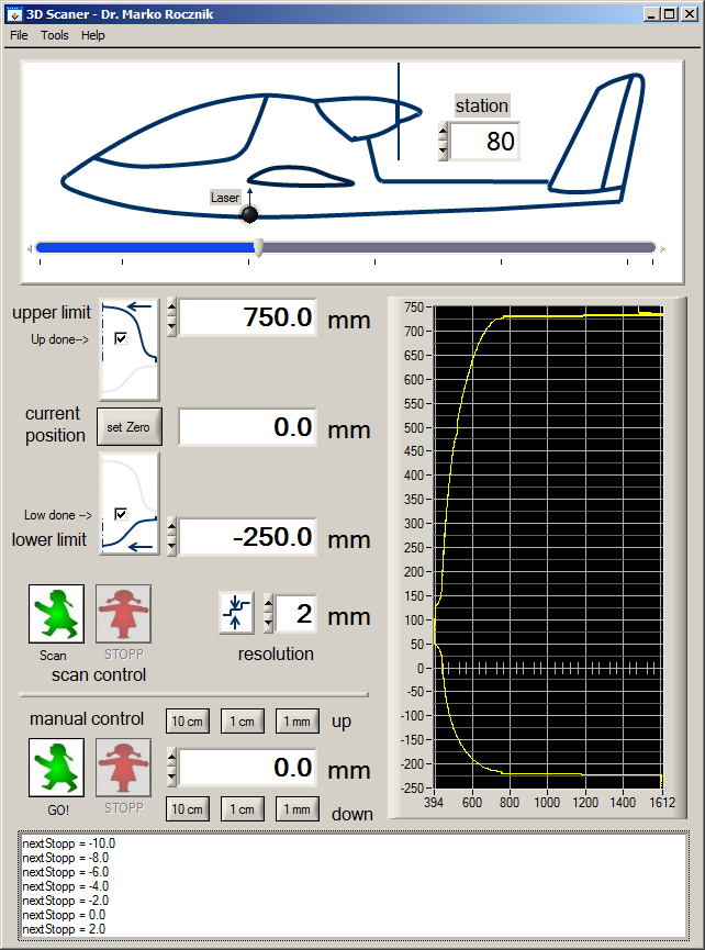
 precision
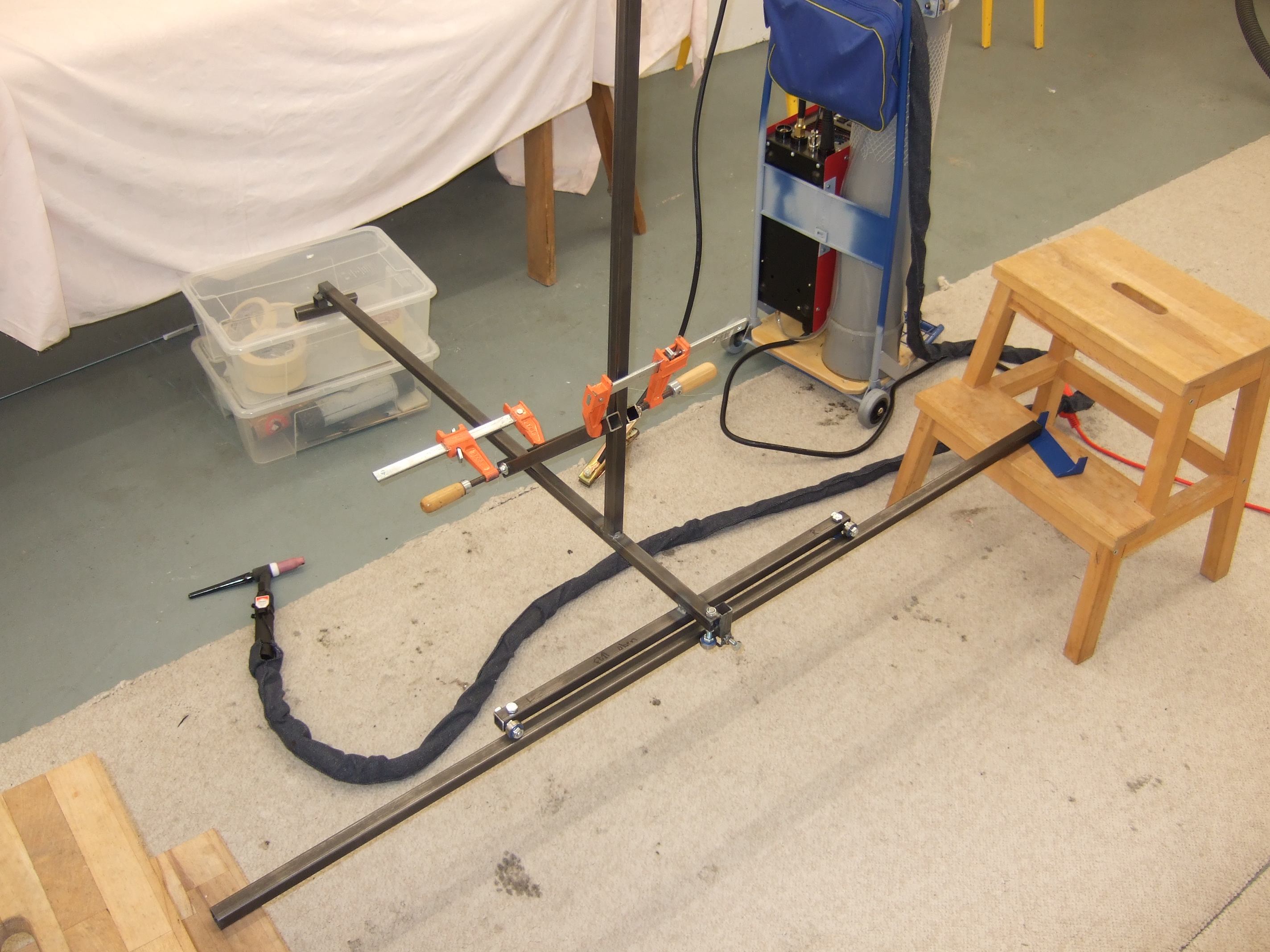 Z- rod alignment
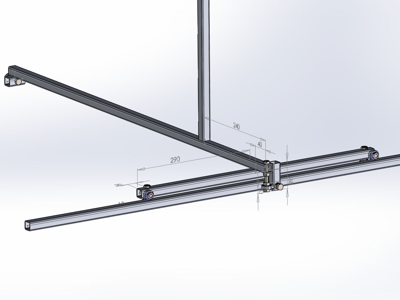
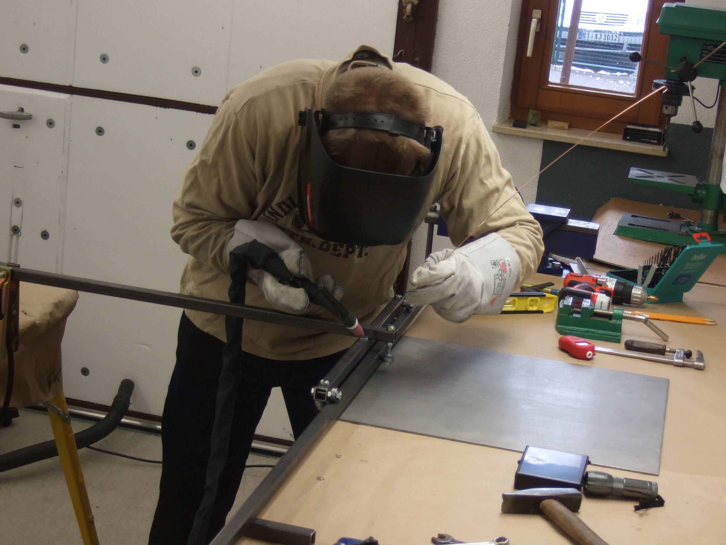 welding
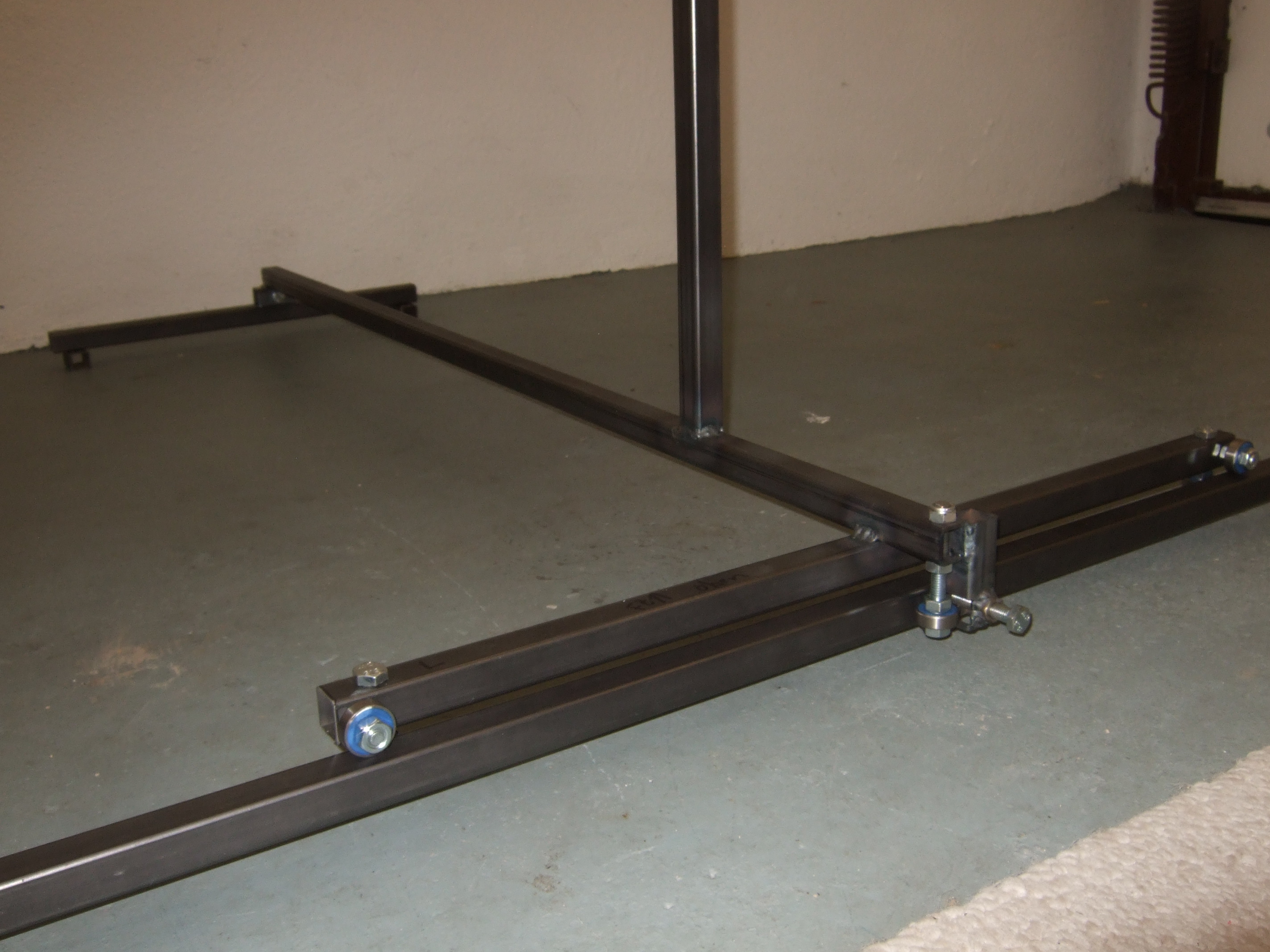
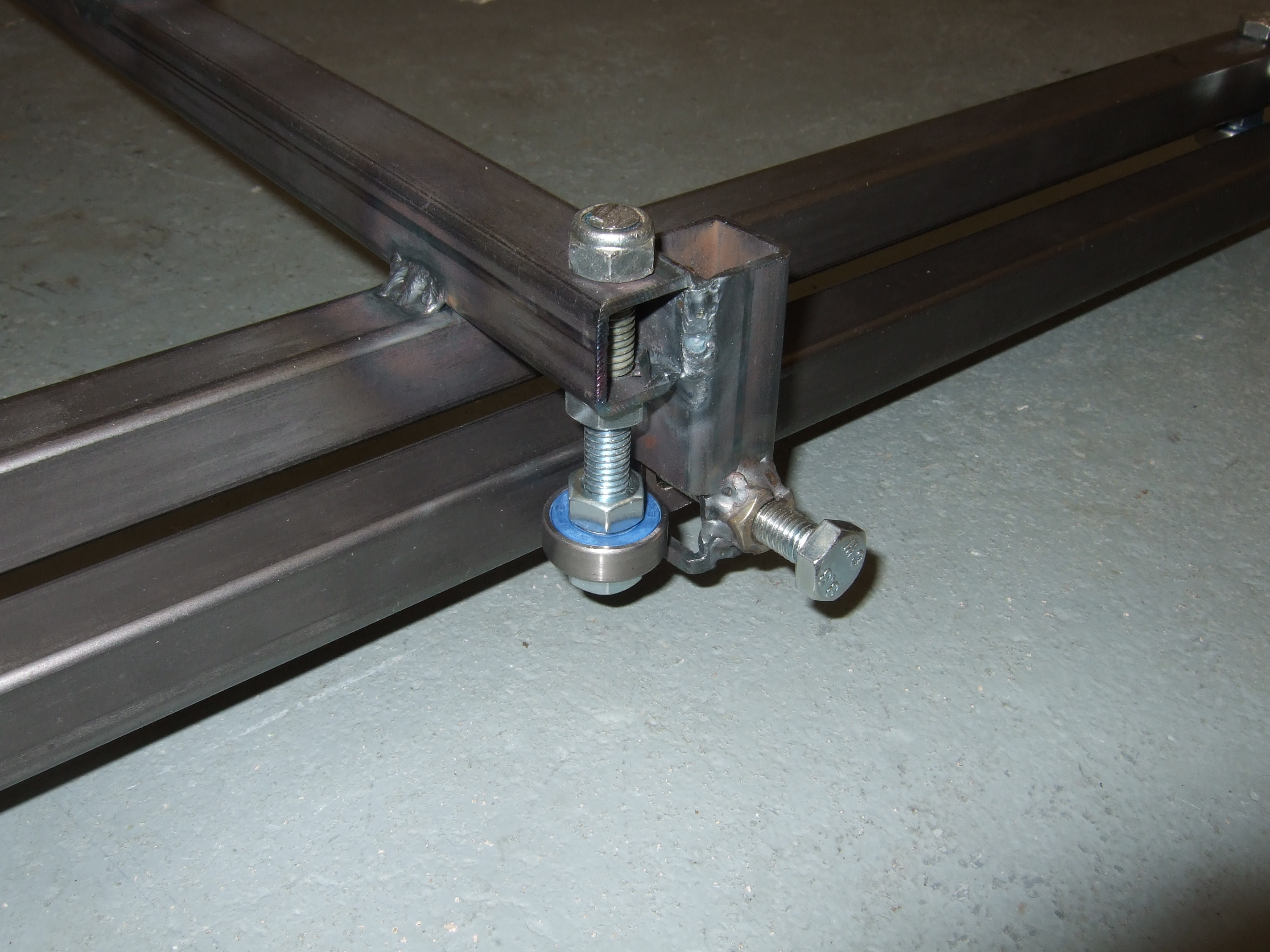 fixture
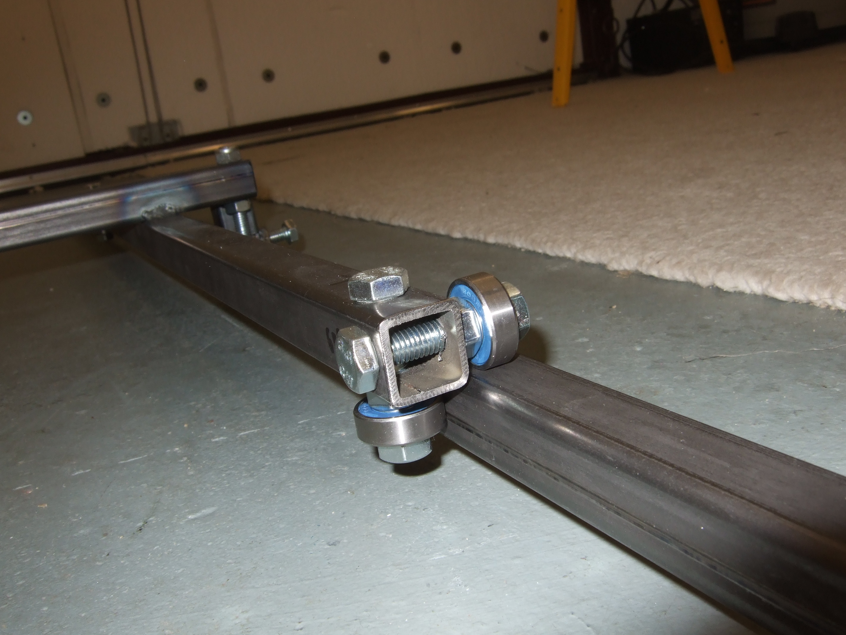
 alignment
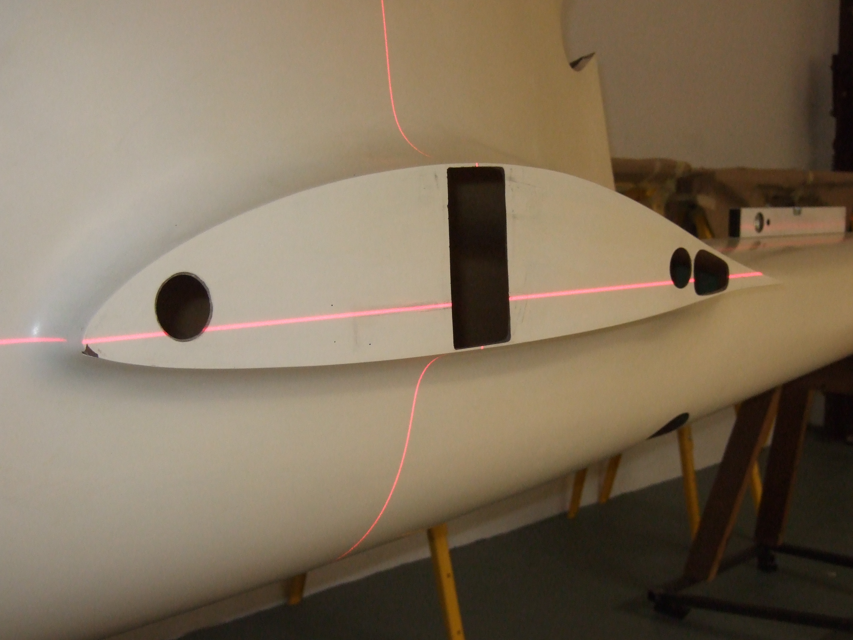
 boom
boom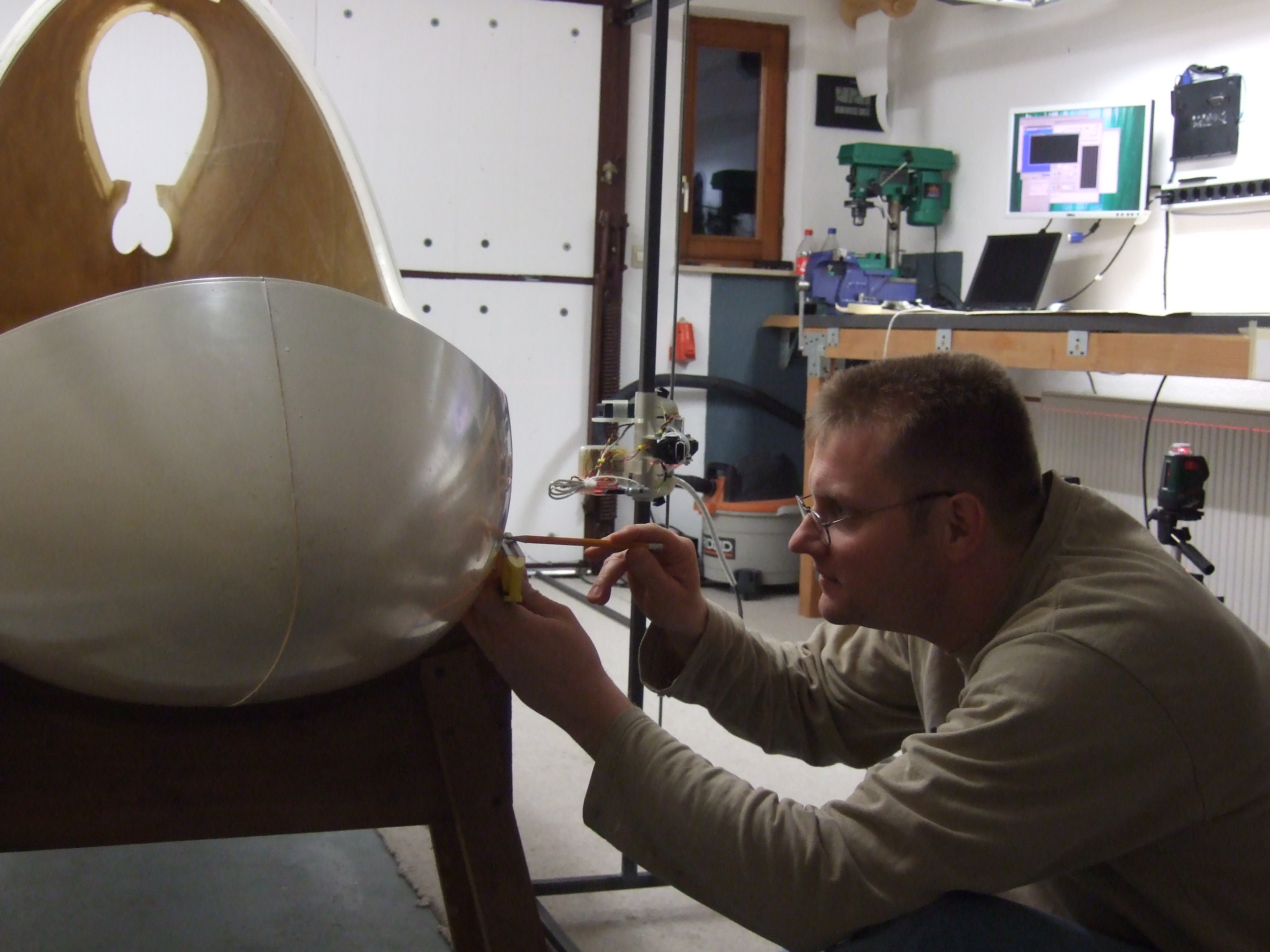
 Dummy canopy layup
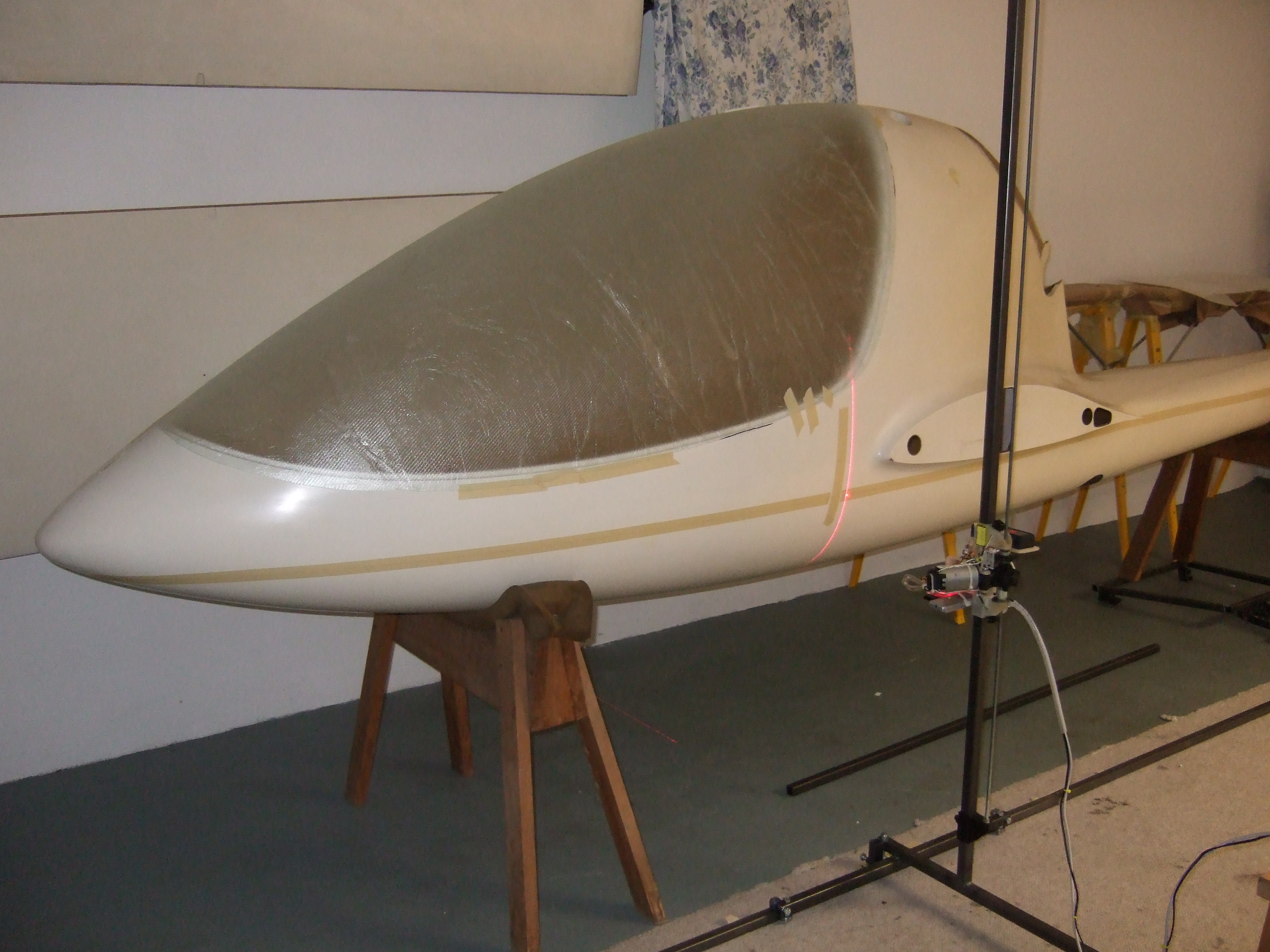
 Bosch cross line laser level
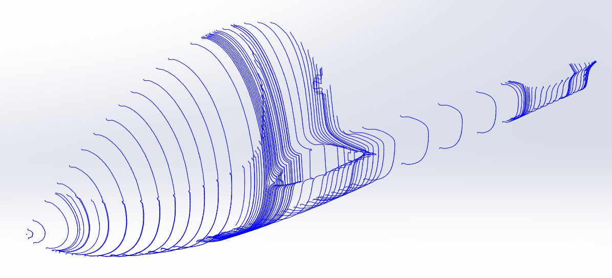
 Video >>
 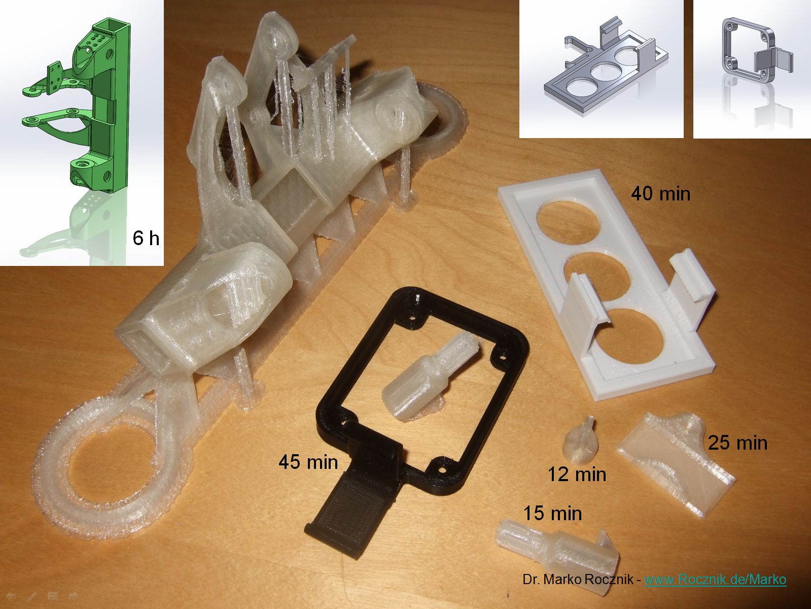 print times
 J-5 Home